User Manual - twentynine
3.3.2
Input Lines (Electrical Specification)
The cameras are equipped with a physical input line, designated as
opto-isolated in
. It is opto-isolated and
can be accessed via the power and I/O interface receptacle on the back of the device. Table 14 shows the
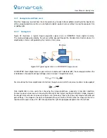
operational limits of the input line, while Figure 22 shows its electrical scheme.
Description
Limits
Recommended operating voltage
+0 to +24 VDC
Voltage level representing logical 0
+0 to +1.4 VDC
Region where the transition threshold occurs; the logical state
is not defined in this region
> +1.4 to +2.2 VDC
Voltage level representing logical 1
> +2.2 VDC
Absolute maximum; the camera may be damaged when the
absolute maximum is exceeded
+30.0 VDC
The current draw for each input line
5 to 15 mA
Table 14: Electrical specification for trigger input (operational limits)
10nF
10R
180R
BF545C
TRI
Opto-isolated In
GND for opto-isolated I/O
Camera
External GND
TLP2366
Figure 22: Trigger input scheme
Caution
Exceeding the limits shown in Table 14 or reneging the wiring polarity shown in
Figure 22 can seriously damage the device!
32
SMARTEK Vision | User Manual - twentynine | Doc. v1.0.2


