SMA Solar Technology AG
8 Power Control
User Manual
SCCP-JP-BA-A4-en-12
55
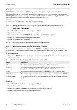
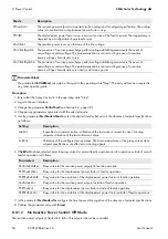
8.2.1.3 Reactive Power Control with Setpoint Command via Modbus Protocol:
VArCtlCom Mode
The reactive power setpoint is received by the Sunny Central via the Power Reducer Box or the Power Plant Controller.
The setpoint is transmitted as a percentage and converted to kVAr in the device.
If the Sunny Central has not received any signal for the last five minutes, the error message
Q-VArModFailStt
will be
displayed (see Section 8.2.2, page 63).
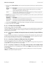
8.2.1.4 Reactive Power Control with Setpoint Command via Modbus Protocol: PFCtlCom
Mode
The reactive power setpoint is received by the Sunny Central via the Power Reducer Box or the Power Plant Controller.
The setpoint is transmitted as a displacement power factor cos φ.
If the Sunny Central has not received any signal for the last five minutes, an error message will be displayed in the
instantaneous value
Q-VArModFailStt
8.2.1.5 Reactive Power Control with Absolute Value: VArCnst Mode
The
Q-VAr
parameter is used to set the reactive power setpoint. The permitted range of the parameter
Q-VAr
is between
‒Qmax
and
+Qmax
.
8.2.1.6 Reactive Power Control as a Percentage of the Nominal Power: VArCnstNom
Mode
The parameter
Q-VArNom
is used to set the reactive power setpoint in %. The parameter
Q-VArNom
refers to
Pmax
.
If the calculated amount of reactive power exceeds the predefined value of
Qmax
, the power will be limited to
Qmax
.
If the calculated amount of reactive power falls below the predefined value of
‒Qmax
, the power will be limited to
‒Qmax
.
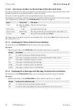
8.2.1.7 Reactive Power Setpoint via Standard Signal: VArCnstNomAnIn Mode
The reactive power setpoint is set via an analog signal at the input terminals for setpoint specification (see Sunny Central
installation manual). This is usually implemented by a ripple control signal.
The analog value is converted into a reactive power setpoint. The electrical current strength of the connected signal
determines the setpoint.
The analog measured values must be between 4 mA and 19 mA. If the analog signal is less than 2 mA, an error message
will be displayed in the instantaneous value
Q
-
VArModFailStt
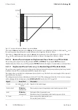
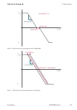
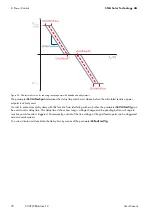
The analog value is converted to a setpoint for power limitation. Here, the
Qmax
parameter forms the end point of the
linear characteristic curve.
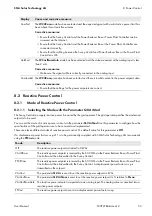
Signal
Power limit
Description
< 2 mA
Last valid mean value or
0 kVAr after restart
Signal is in the invalid range.
2 mA to 4 mA
− Pmax
The maximum amount of negatively excited reactive power is fed in.
4 mA
− Pmax
Start point of the characteristic curve
The maximum amount of negatively excited reactive power is fed in.
11.5 mA
0 kVAr
Zero-crossing of the characteristic curve
No reactive power is fed in.
> 19 mA
+Pmax
End point of the characteristic curve
The maximum amount of positively excited reactive power is fed in.
Содержание Sunny Central 500CP-JP
Страница 108: ...www SMA Solar com SMA Solar Technology...

