background image

Installation

SMA


Technologie AG

Page 24

SB25_30-11:SE0307

Installation Guide

6.2.1 Connecting the AC Output

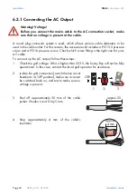
A round plug connector system is used, which allows various cable diameters to be
used in the cable outlet. For this reason, the accessories kit includes a PG13.5 pressure
screw and a PG16 pressure screw. Check which screw fitting is the right one for your
AC cable.
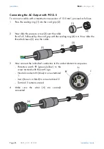
To connect up the AC output, follow these steps:
1.

Check the grid voltage. If this is higher than 253 V, the Sunny Boy will not be fully
operational. In this case, contact the local grid operator for assistance. 

2.

Isolate the grid connection (switch the line circuit
breaker to its "off" position), make sure it cannot
be switched back on, and test to make sure no
voltage is present.

3.

Peel off approximately 30 mm of the cable
jacket. Shorten L and N by 5 mm.

4.

Strip approximately 4 mm of the cable's
insulation.

Warning! Voltage!
Before you connect the mains cable to the AC connection socket, make
sure that no voltage is present at the cable.

Off!

approx. 25 

approx. 

4 mm

Содержание Sunny Boy SB 2500

Страница 1: ...Sunny Boy SB 2500 and SB 3000 String Inverter for Photovoltaic Plants Installation Guide Version 1 0 SB25_30 11 SE0307 IMEN SB25_30...

Страница 2: ......

Страница 3: ...12 5 Installation Requirements 13 5 1 Installation Location Requirements 13 5 2 PV Generator Requirements 15 5 3 Low Voltage Grid AC 15 6 Installation 21 6 1 Mounting the Device 21 6 2 Electrical Inst...

Страница 4: ...0 41 8 4 Operating Parameters 42 8 4 1 Explanation of the Operating Parameters 42 8 4 2 Parameter Settings for Germany 45 8 4 3 Country specific Parameter Settings 47 8 4 4 Fixed Parameters 48 8 5 Cer...

Страница 5: ...is document note the following explanation of the symbols used This symbol indicates an example This symbol indicates a note which if ignored will make the procedure or operation more difficult This s...

Страница 6: ...Explanation of the Symbols Used SMA Technologie AG Page 6 SB25_30 11 SE0307 Installation Guide...

Страница 7: ...tallation and commissioning of the SMA Sunny Boy SB 2500 and Sunny Boy SB 3000 inverters The Sunny Boy is equipped with the SMA grid guard This is a type of automatic disconnection device This means t...

Страница 8: ...g to either device type The device will be specified with its full name if the information only refers to that particular device Warning The Sunny Boy is designed for operation in grid connected PV sy...

Страница 9: ...t the capacitors have been discharged The Sunny Boy must be disconnected from the grid and precautions must be taken to prevent the grid being accidentally reconnected In addition the connections to t...

Страница 10: ...Safety Instructions SMA Technologie AG Page 10 SB25_30 11 SE0307 Installation Guide...

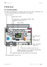
Страница 11: ...over removed Varistors section 9 Communication socket RS232 RS485 NLM Piggy Back radio section 11 Sunny Display Operating status LEDs Jumper slot for communication Communication socket Plug socket AC...

Страница 12: ...Overview SMA Technologie AG Page 12 SB25_30 11 SE0307 Installation Guide 4 2 External Dimensions 225 mm 470 mm 490 mm...

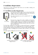
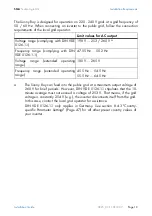
Страница 13: ...increased ambient temperature can reduce the yield of the PV system Installing the unit in badly ventilated warm indoor locations may also reduce yield The Sunny Boy is designed to be mounted on a ver...

Страница 14: ...e noises during operation which could be perceived as a nuisance if installed in a living area Warning high voltage Unintentionally pulling out the DC plug connectors under load can damage the plugs a...

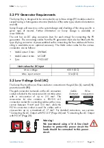
Страница 15: ...des for the various connectors are as follows 5 3 Low Voltage Grid AC The Sunny Boy must have a three conductor connection to the grid live L neutral N protective earth PE The grid connection terminal...

Страница 16: ...ces the maximum current load Loop impedance Z in the event of a body contact this limits the current that can flow and therefore determines the response behavior of the circuit breaker Sufficient dist...

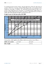
Страница 17: ...dimensioning the cable cross section so that output losses do not exceed 1 at nominal power Output losses as a function of cable length and cross section are shown in the graphs below Multi wire cabl...

Страница 18: ...Technologie AG Page 18 SB25_30 11 SE0307 Installation Guide Output Losses of the Sunny Boy SB 3000 Cable cross section 1 5 mm 2 5 mm Max length 7 5 m 12 5 m Do not use cables where losses will exceed...

Страница 19: ...Hz Voltage range extended operating range 180 V 265 V Frequency range extended operating range 45 5 Hz 54 5 Hz 55 5 Hz 64 5 Hz a The Sunny Boy can feed into the public grid at a maximum output voltage...

Страница 20: ...Installation Requirements SMA Technologie AG Page 20 SB25_30 11 SE0307 Installation Guide...

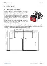
Страница 21: ...the bracket using 6 mm x 50 mm hexagon bolts to DIN 571 standard stainless steel type and with wall anchors type SX 8 When selecting the mounting materials be sure to take into account the weight of t...

Страница 22: ...te so that it cannot be moved sideways 3 Secure the Sunny Boy in position by screwing the supplied M6x10 bolt into the central threaded hole at the bottom of the bracket 3 4 Make sure that the Sunny B...

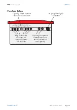
Страница 23: ...SB25_30 11 SE0307 Page 23 View from below Plug and socket connector for connection of the solar modules Opening for optional communication via RS232 RS485 or radio PG16 AC plug for the grid connectio...

Страница 24: ...teps 1 Check the grid voltage If this is higher than 253 V the Sunny Boy will not be fully operational In this case contact the local grid operator for assistance 2 Isolate the grid connection switch...

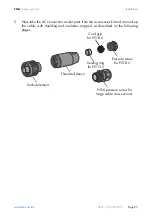
Страница 25: ...nection socket parts from the accessories kit and connect up the cable with shielding and insulation stripped as described on the following pages Socket element Threaded sleeve Sealing ring for PG13 5...

Страница 26: ...crew 3 over the cable first of all followed by the cord grip with the sealing ring 4 in it Now slide the threaded sleeve 5 over the cable 3 Now connect the individual conductors to the socket element...

Страница 27: ...the Sunny Boy immediately close the socket element using the cap supplied in the accessories kit If the Sunny Boy is already installed you can now connect up the fully assembled AC connection socket t...

Страница 28: ...1 onto the cable Now slide the threaded sleeve 2 over the cable 2 Now connect the individual conductors to the socket element in sequence Protective earth PE green yellow to the screw terminal with th...

Страница 29: ...t using the cap supplied in the accessories kit If the Sunny Boy is already installed you can now connect up the fully assembled AC connection socket to the flange plug on the Sunny Boy To do this rem...

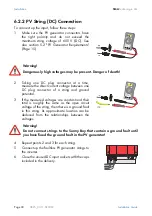
Страница 30: ...and ground potential 3 If the measured voltages are constant and their total is roughly the same as the open circuit voltage of the string then there is a ground fault in this string Its approximate l...

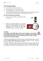
Страница 31: ...nerator for assistance If despite checking the string voltages the LED signal occurs again when the PV generator is connected to the Sunny Boy disconnect the PV generator from the Sunny Boy again and...

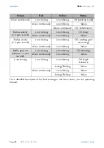
Страница 32: ...lization flashes quickly 3 x per second is not shining is not shining OK stop shines continuously is not shining failure flashes slowly 1 x per second is not shining is not shining OK waiting grid mon...

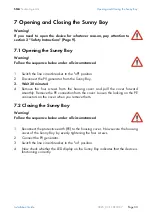
Страница 33: ...e PE connectors on the cover when you remove them 7 2 Closing the Sunny Boy 1 Reconnect the protective earth PE to the housing cover Now secure the housing cover of the Sunny Boy by evenly tightening...

Страница 34: ...Opening and Closing the Sunny Boy SMA Technologie AG Page 34 SB25_30 11 SE0307 Installation Guide...

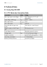
Страница 35: ...Input voltage MPP range UPV 224 V 600 V Max input current IPV max 12 A Max input power PDC 2700 W Recommended total generator power 3000 Wp for central Europe All pole isolator on the DC input side DC...

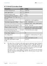
Страница 36: ...Power factor based on the current s fundamental frequency cos phi 1 at nominal power output Overvoltage category III Test voltage DC 1 95 kV 1 s routine testing 5 s type testing Test surge voltage 4...

Страница 37: ...tage MPP range UPV 268 V 600 V Max input current IPV max 12 A Max input power PDC 3200 W Recommended total generator power 3600 Wp for central Europe All pole isolator on the DC input side DC plug con...

Страница 38: ...Power factor based on the current s fundamental frequency cos phi 1 at nominal power output Overvoltage category III Test voltage DC 1 95 kV 1 s routine testing 5 s type testing Test surge voltage 4...

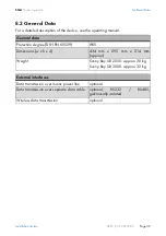
Страница 39: ...General data Protection degree DIN EN 60529 IP65 Dimensions w x h x d 434 mm x 295 mm x 214 mm approx Weight Sunny Boy SB 2500 approx 30 kg Sunny Boy SB 3000 approx 32 kg External interfaces Data tran...

Страница 40: ...Efficiency of the Sunny Boy SB 2500 The efficiency of the Sunny Boy SB 2500 depends mainly on the input voltage of the connected PV strings The lower the input voltage the higher the efficiency Effici...

Страница 41: ...Efficiency of the Sunny Boy SB 3000 The efficiency of the Sunny Boy SB 3000 depends mainly on the input voltage of the connected PV strings The lower the input voltage the higher the efficiency Effic...

Страница 42: ...on of the AntiIsland process alternative anti islanding process which is deactivated for Germany AntiIsland Freq Repetition rate of the AntiIsland process alternative anti islanding process which is d...

Страница 43: ...o use the data from the old device I NiTest Setting the impulse for impedance monitoring This parameter only functions when the Sunny Boy is deactivated disconnected on the AC side or in Stopp mode Sp...

Страница 44: ...lay wear If after disconnection from the grid and in the absence of any further faults the inverter does not automatically reconnect to the grid this parameter can be decreased in small steps It must...

Страница 45: ...ge the parameters of your Sunny Boy without express authorization and instructions Name Short descr Value range Factory setting Sunny Boy SB 2500 Sunny Boy SB 3000 ACVtgRPro V 230 300 253 253 AntiIsla...

Страница 46: ...Min V 180 300 198 198 Upv Start V 250 600 290 600 300 330 Usoll Konst V 250 600 600 600 Parameters designated with are safety related grid monitoring parameters To change the SMA grid guard parameter...

Страница 47: ...00 Name Short descr Country settings Germany Great Britain Spain Default GER VDE0126 1 1 GB G83 SP RD1663 dFac Max Hz s 4 0 2 2 dZac Max mOhm 700 350 350 Fac delta Hz 2 45 0 5 0 98 Fac delta Hz 0 19 0...

Страница 48: ...e 8 4 4 Fixed Parameters The following parameters are displayed in the parameter list but cannot be changed Name Short descr Value range Sunny Boy SB 2500 Sunny Boy SB 3000 Fac Pderating Fac Tavg ms 1...

Страница 49: ...pliant with the following standards EMC Emission DIN EN 61000 6 3 2002 08 DIN EN 61000 6 4 2002 08 DIN EN 55022 2003 09 Class B Utility Interference DIN EN 61000 3 3 2002 05 DIN EN 61000 3 2 2001 12 I...

Страница 50: ...stallation Guide 8 5 2 SMA Grid Guard Certificate The Sunny Boy is equipped with the automatic disconnection device SMA grid guard which has been awarded a certificate of confidence by the Professiona...

Страница 51: ...is no ground fault in the PV generator 1 Disconnect the Sunny Boy from the low voltage grid switch the line circuit breaker to its off position or pull out the AC plug Make sure the grid cannot be ina...

Страница 52: ...ctive caps or using sufficient high voltage insulating tape If you did not find any ground fault in the PV generators it is likely that one of the thermally monitored varistors has lost its protective...

Страница 53: ...pecially manufactured for use in the Sunny Boy and are not commercially available They must be ordered directly from SMA Technologie AG SMA order code SB TV4 Warning If no spare varistors are availabl...

Страница 54: ...ion Guide If no ground fault and no defective varistor were found there is probably a fault in the Sunny Boy In this case contact the SMA Hotline to discuss what to do next 14 Now check whether the LE...

Страница 55: ...r the thermal suitability of the line circuit breaker still needs to be checked Example for the thermal rating for a line circuit breaker in a photovoltaic power generating system operated in parallel...

Страница 56: ...0 91 Reduction factor when 9 circuit breakers are arranged side by side without gaps 0 772 Increase in nominal current as a result of ambient temperatures of 40 C in the circuit breaker panel 1 073 R...

Страница 57: ...en the circuit breakers This would mean that the reduction factor is 0 98 instead of 0 77 As a result the maximum current carrying capacity would be 15 1 A In addition to the thermal rating of the cir...

Страница 58: ...Rating for a Line Circuit Breaker SMA Technologie AG Page 58 SB25_30 11 SE0307 Installation Guide...

Страница 59: ...tails on the required cable type Which of the inverter s connections are used Whether jumpers need to be mounted and if so which jumpers Whether the PE needs to be connected to the cable shield The ne...

Страница 60: ...trip D as described in the connection plan of the communication device Note down the connector color coding for the respective pin numbers Connecting the receiver incorrectly can cause the devices to...

Страница 61: ...per functions can be found in the communication device manual A Housing feed through in the base of the Sunny Boy B Cable route gray surface C PE connector D Screw terminals for connection of the comm...

Страница 62: ...The Communication Interface SMA Technologie AG Page 62 SB25_30 11 SE0307 Installation Guide...

Страница 63: ...t our hotline Have the following information available when you contact SMA Inverter type Type and number of modules connected Communication method Serial number of the Sunny Boy Blink code or display...

Страница 64: ...otection conditions Altering the product or supplied software without authority The product malfunctions due to operating attached or neighboring devices beyond statutory limit values In case of unfor...

Страница 65: ......
Страница 66: ...A Technologie AG Hannoversche Strasse 1 5 34266 Niestetal Germany Tel 49 561 9522 4000 Fax 49 561 9522 4040 E Mail Info SMA de Freecall 800 SUNNYBOY Freecall 800 78669269 Innovation in Systems Technol...

Отзывы: