background image

2  Safety

SMA Solar Technology AG

Operating manual

SB55-LV-JP-41-BE-en-13

9

2

Safety

2.1

Intended Use

The Sunny Boy is a transformerless PV inverter with 2 MPP trackers, which convert the direct current
of the PV array into grid-compliant alternating current and feeds it into the utility grid.
The product is suitable for indoor and outdoor use.
The product must only be operated with PV modules and cables that have been recommended and
sold by the distributor. Do not connect any energy sources other than PV modules to the product.
The product is not equipped with an integrated transformer and therefore has no galvanic isolation.
The product must not be operated with PV modules whose outputs are grounded. This can cause
the product to be destroyed. The product may be operated with PV modules whose frame is
grounded.
PV modules with a high capacity to ground may only be used if their coupling capacity does not
exceed 3.4 μF.
All components must remain within their permitted operating ranges and their installation
requirements at all times.
The product is exclusively approved for the Japanese market and must only be used in Japan.
Use SMA products only in accordance with the information provided in the enclosed
documentation and with the locally applicable laws, regulations, standards and directives. Any
other application may cause personal injury or property damage.
Alterations to the SMA products, e.g., changes or modifications, are only permitted with the express
written permission of SMA Solar Technology AG. Unauthorized alterations will void guarantee and
warranty claims and in most cases terminate the operating license. SMA Solar Technology AG
shall not be held liable for any damage caused by such changes.
Any use of the product other than that described in the Intended Use section does not qualify as the
intended use.
The enclosed documentation is an integral part of this product. Keep the documentation in a
convenient, dry place for future reference and observe all instructions contained therein.
This document does not replace and is not intended to replace any local, state, provincial, federal
or national laws, regulations or codes applicable to the installation, electrical safety and use of the
product. SMA Solar Technology AG assumes no responsibility for the compliance or non-
compliance with such laws or codes in connection with the installation of the product.
The type label must remain permanently attached to the product.

2.2

IMPORTANT SAFETY INSTRUCTIONS

Keep the manual for future reference.
This section contains safety information that must be observed at all times when working.
The product has been designed and tested in accordance with international safety requirements. As
with all electrical or electronical devices, there are residual risks despite careful construction. To
prevent personal injury and property damage and to ensure long-term operation of the product,
read this section carefully and observe all safety information at all times.

Содержание SUNNY BOY 5.5-JP

Страница 1: ...SUNNY BOY SB55 LV JP 41 BE en 13 Version 1 3 ENGLISH Operating manual SUNNY BOY 5 5 JP...

Страница 2: ...not apply in all cases under some statutes and thus the above exclusion may not apply Specifications are subject to change without notice Every attempt has been made to make this document complete ac...

Страница 3: ...ivery 13 4 Additionally Required Materials and Equipment 14 5 Product Overview 15 5 1 Product Description 15 5 2 Symbols on the Product 16 5 3 Interfaces and Functions 17 5 4 LED Signals 18 5 5 System...

Страница 4: ...cal Network 46 9 2 Logging In and Out of the User Interface 46 9 3 Start Page Design of the User Interface 48 9 4 Activating the Smart Inverter Screen 50 9 5 Starting the Installation Assistant 51 9 6...

Страница 5: ...Table of Contents SMA Solar Technology AG Operating manual SB55 LV JP 41 BE en 13 5 15 Contact 92...

Страница 6: ...l applicable laws standards and directives Knowledge of and compliance with this document and all safety information Knowledge of building structures and building materials 1 3 Content and Structure o...

Страница 7: ...ed persons only 1 6 Typographical Elements in the Document Typography Use Example bold Messages Terminals Elements on a user interface Elements to be selected Elements to be entered Connect the insula...

Страница 8: ...rating Efficiency and derating behavior of the SMA inverters Technical Information Parameters and Measured Values Overview of all inverter operating parameters and their configura tion options Technic...

Страница 9: ...the SMA products e g changes or modifications are only permitted with the express written permission of SMA Solar Technology AG Unauthorized alterations will void guarantee and warranty claims and in...

Страница 10: ...n opening the product High voltages are present in the live parts and cables inside the product during operation Touching live parts and cables results in death or lethal injuries due to electric shoc...

Страница 11: ...nditions In this state switching operations can cause a fire inside the product or explosion Death or lethal injuries due to hot or flying debris can result In the event of a fault do not perform any...

Страница 12: ...mounted Transport and lift the product carefully Take the weight of the product into account Wear suitable personal protective equipment for all work on the product NOTICE High costs due to inappropr...

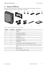
Страница 13: ...or damaged B C D _ E G I H J K A F Figure 1 Components included in the scope of delivery Position Quantity Designation A 1 Inverter B 1 Wall mounting bracket C 4 Pan head screw M5x12 D 4 Washer M5 E...

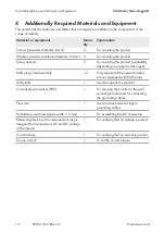
Страница 14: ...ailability depending on support surface type RJ45 plugs field assembly 1 2 Only required if the network cables are not equipped with RJ45 plugs Utility knife 1 Used to unpack the product Cross head sc...

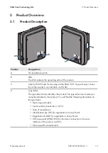
Страница 15: ...the inverter s user interface via WLAN D Type label The type label clearly identifies the product The type label must remain per manently attached to the product You will find the following informati...

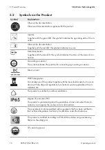
Страница 16: ...s the position for connecting a grounding conductor Direct current WEEE designation Do not dispose of the product together with the household waste but in accor dance with the disposal regulations for...

Страница 17: ...rate of 100 Mbps and enables optimum communication between Speedwire devices within systems The products supports the encrypted system communication with SMA Speedwire Encrypted Communication In orde...

Страница 18: ...y supply from the PV modules at all times to increase yields in shaded systems SMA ShadeFix is enabled by default The time interval of SMA ShadeFix is usually six minutes This means that the inverter...

Страница 19: ...can switch off the dynamic power display via the green LED The green LED is off The inverter is not feeding into the utility grid The red LED is glowing Event occurred If an event occurs a distinct e...

Страница 20: ...itry Overview SUNNY BOY 3 SUNNY BOY 1 9 Grounding conductor Line conductor Neutral conductor Cabel DC 600 V Cabel DC 600 V PV MODULES DISTRIBUTION BOARD GRID CONNECTION POINT with energy meter of the...

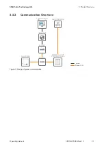
Страница 21: ...nology AG Operating manual SB55 LV JP 41 BE en 13 21 5 5 2 Communication Overview SUNNY PORTAL SUNNY BOY Ethernet LAN REMOTE OUTPUT CONTROL DEVICE GRID OPERATOR INTERNET ROUTER SWITCH Internet Figure...

Страница 22: ...dimensions of the product see Section 14 page 89 The mounting location must not be exposed to direct solar irradiation If the product is exposed to direct solar irradiation the exterior plastic parts...

Страница 23: ...g UP 90 30 172 298 470 121 9 x 18 9 9 x 18 435 9 x 18 107 5 126 5 93 155 0 25 155 0 25 217 5 217 5 120 0 5 150 0 5 311 0 5 Figure 5 Position of the anchoring points Dimensions in mm Recommended cleara...

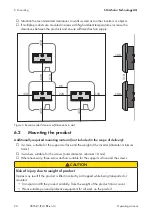
Страница 24: ...in mm 6 2 Mounting the product Additionally required mounting material not included in the scope of delivery 3 screws suitable for the support surface and the weight of the inverter diameter minimum 6...

Страница 25: ...holes 3 Insert screw anchors into the drill holes if the support surface requires them 4 Secure the wall mounting bracket horizontally using screws and washers UP 5 Hook the inverter into the wall mo...

Страница 26: ...port with protective cap G Connection point for connecting a grounding conductor optional 7 2 AC Connection 7 2 1 Requirements for the AC Connection AC cable requirements as follows Conductor type co...

Страница 27: ...circuit breaker Make sure to observe the maximum permissible fuse protection see Section 14 Technical Data page 89 This will prevent residual voltage from being present at the corresponding cable afte...

Страница 28: ...g cable into the ring terminal lug and crimp using a crimping tool 8 Insert the pan head screw M5x12 incl washer M5 into the screw hole in the ring terminal lug and screw the ring terminal lug with sc...

Страница 29: ...r lethal injuries due to electric shock Ensure that all devices in the same network are integrated in the existing overvoltage protection When laying the network cable outdoors ensure that there is su...

Страница 30: ...or outdoor use Procedure 1 Disconnect the product from voltage sources see Section 10 page 59 2 Unscrew the protective cap from the network port 3 Press the cable support sleeve out of the threaded sl...

Страница 31: ...ue to electric shock Disconnect the inverter from all voltage sources see Section 10 page 59 2 Remove the protective cap from the jack on the inverter 3 Plug the WLAN antenna into the jack and screw t...

Страница 32: ...les generate high DC voltage which is present in the DC cables Touching live DC cables results in death or lethal injuries due to electric shock Do not touch non insulated parts or cables Disconnect t...

Страница 33: ...7 Nominal voltage minimum 600 V Using bootlace ferrules is not allowed Procedure 1 Strip 12 mm of the cable insulation 2 Insert the stripped cable into the DC connector up to the stop When doing so e...

Страница 34: ...he measuring device results in death or lethal injuries due to electric shock Only use measuring devices with a DC input voltage range of 600 V or higher NOTICE Destruction of the inverter due to over...

Страница 35: ...ptional Use of fine stranded conductors You can use an inflexible or a flexible fine stranded conductor When using a fine stranded conductor it has to be double crimped by a ring terminal lug Make sur...

Страница 36: ...hat the open circuit voltage of the PV array does not exceed the maximum input voltage of the inverter 8 Connect the assembled DC connectors to the inverter The DC connectors snap into place 9 Ensure...

Страница 37: ...ected correctly if the DC connectors are released and disconnected incorrectly This can result in the DC conductors or DC plug contacts being exposed Touching live DC conductors or DC plug connectors...

Страница 38: ...ctor To do this insert a flat blade screwdriver blade width 3 5 mm into the side catch mechanism and pry the catch mechanism open 2 3 1 4 Carefully pull the DC connector apart 5 Release the clamping b...

Страница 39: ...the configuration of the inverter in a file Section 9 13 page 56 6 Establish a connection to the user interface of each addi tional inverter in the system Section 9 1 page 43 7 Log into the user inter...

Страница 40: ...the desired firmware is being installed All three LEDs go out again after approximately 90 seconds The green LED starts to flash and if the inverter is connected via Speedwire the blue LED also starts...

Страница 41: ...n the listed configuration options C Configuration options Provides a selection of the various configuration op tions Configuration options On the Configuring the Inverter page different configuration...

Страница 42: ...an adopt the inverter configuration from a file To do this there must be an inverter configuration saved to a file Procedure 1 Select the configuration option Adopting configuration from a file 2 Sele...

Страница 43: ...ered a message might appear indicating that the connection to the user interface of the product is not secure SMA Solar Technology AG guarantees the security of the user interface Continue loading the...

Страница 44: ...the menu 3 Scan the QR Code on you product via the SMA 360 App The end device automatically connects to the product The web browser of your end device opens and the login page of the user interface is...

Страница 45: ...ssigned by the DHCP server router identification via network scanner software or network configuration of the router Access address for Apple and Linux systems SMA serial number local e g SMA012345678...

Страница 46: ...oduct into the local network with the aid of the installation assistant An end device e g computer tablet PC or smartphone must be available The end device must be in the same local network as the pro...

Страница 47: ...If you assign a password for the user group Installer via the user interface of the inverter the same password must also be used as the system password Assign a uniform installer password to all SMA...

Страница 48: ...9 Operation SMA Solar Technology AG Operating manual SB55 LV JP 41 BE en 13 48 9 3 Start Page Design of the User Interface C B E F D A Figure 10 Design of the user interface s home page example...

Страница 49: ...s viewlet However only the higher priority event is displayed If for example there is a Warning and an Error present at the same time only the Error will be displayed Device configuration Various sett...

Страница 50: ...n the PV system F Status display The various areas display information on the current status of the PV system Device status Displays whether the inverter is currently in a fault free operating state o...

Страница 51: ...scription A Configuration steps Overview of the installation assistant steps The number of steps depends on the type of device and the additionally installed modules The current step is highlighted in...

Страница 52: ...work button in the WLAN tab 6 Select Activate WPS 7 Select Save and next and exit the installation assistant The WPS function is activated and the automatic connection to the network can be establishe...

Страница 53: ...off completely the inverter must be connected to a computer or router via Ethernet Procedure To switch on the WLAN direct connection in the parameter group PV system communication WLAN select the para...

Страница 54: ...r interface see Section 9 2 page 46 3 Call up the menu Device Parameters 4 Select Edit parameters 5 In the parameter group User Rights Access Control change the password of the desired user group 6 Se...

Страница 55: ...vice and the inverter the Modbus interface of the inverter is automatically enabled and the communication ports 502 are set Changes to the Modbus configuration may cause the communication between the...

Страница 56: ...al In order to disable the SMA ShadeFix feature in the parameter group DC side DC settings SMA ShadeFix set the parameter SMA ShadeFix switched on to Off 9 13 Saving the Configuration in a File You ca...

Страница 57: ...date You have the following options to update the firmware Update the firmware with the existing update file via the user interface of the inverter Search and install the firmware via the user interfa...

Страница 58: ...he inverter must be connected to the Internet Procedure 1 Open the user interface see Section 9 1 page 43 2 Log into the user interface as an Installer see Section 9 2 page 46 3 Click on Edit paramete...

Страница 59: ...the measuring device due to overvoltage Overvoltage can damage a measuring device and result in voltage being present in the enclosure of the measuring device Touching the live enclosure of the measur...

Страница 60: ...connectors Ensure that the DC connectors are in perfect condition and that none of the DC conductors or DC plug contacts are exposed Carefully release and remove the DC connectors as described in the...

Страница 61: ...10 Disconnecting the Inverter from Voltage Sources SMA Solar Technology AG Operating manual SB55 LV JP 41 BE en 13 61 9 Unscrew the AC connector and pull it out of the jack for the AC connection 2 1...

Страница 62: ...e product NOTICE Damage to the product due to cleaning agents The use of cleaning agents may cause damage to the product and its components Clean the product and all its components only with a cloth m...

Страница 63: ...tion 15 Contact page 92 2 Open the user interface see Section 9 1 page 43 3 Enter the PUK instead of the password into the field Password 4 Select Login 5 Call up the menu Device Parameters 6 Click on...

Страница 64: ...d overvoltage fast Corrective measures Check whether the grid voltage at the connection point of the inverter is permanently in the permissible range If the grid voltage is outside the permissible ran...

Страница 65: ...tage fast The utility grid has been disconnected the AC cable is damaged or the grid voltage at the connection point of the inverter is too low The inverter has dis connected from the utility grid Cor...

Страница 66: ...with a change of the monitored operating limits If the grid voltage is permanently within the permissible range and this message is still displayed contact the Service 205 PLL not within limits The u...

Страница 67: ...agree with an adjustment of the voltage at the feed in point or with a change of the monitored operating limits If the grid voltage is permanently within the permissible range and this message is stil...

Страница 68: ...rter has dis connected from the utility grid Corrective measures If possible check the power frequency and observe how often fluctuations occur If fluctuations occur frequently and this message is dis...

Страница 69: ...e range The inverter has dis connected from the utility grid Corrective measures If possible check the power frequency and observe how often fluctuations occur If fluctuations occur frequently and thi...

Страница 70: ...re that the circuit breaker is switched on Ensure that the AC cable is not damaged and that it is connected correctly 1501 Reconnection fault grid The value of a grid parameter you have set does not c...

Страница 71: ...voltage exceeds the maximum input voltage of the inverter ensure that the PV array has been correctly rated or contact the installer of the PV array If this message is repeated frequently contact the...

Страница 72: ...he PV array is correctly rated 6001 6416 Self diagnosis Interference device The cause must be determined by the Service Corrective measures Contact the Service 6501 6502 6509 Self diagnosis Overtemper...

Страница 73: ...e parameter file to the correct folder again 7105 Param setting failed Parameters could not be set using the memory card The inverter continues to feed in Corrective measures Ensure that the parameter...

Страница 74: ...nternal memory 7333 Update transport failed Update file could not be copied to the inverter s internal memory In the event of connection with the inverter via WLAN a poor connection quality can be the...

Страница 75: ...rrective measures Log in as Installer Import configuration file again 7350 Transfer of a configuration file has started The configuration file is being transferred 7353 Update time zone database The i...

Страница 76: ...ex cessive temperature Corrective measures Clean the cooling fins on the rear of the enclosure and the air ducts on the top using a soft brush Ensure that the inverter has sufficient ventilation Ensur...

Страница 77: ...iled tn0 No time information could be called up from the set NTP server Corrective measures Ensure that the NTP server was configured correctly Ensure that the inverter is integrated into a local netw...

Страница 78: ...o the network switch or DHCP server router has changed An additional error message may be displayed 10252 Interface communication disrupted There is no valid signal on the network line Corrective meas...

Страница 79: ...maged and that the network connectors are correctly plugged Ensure that the DHCP server router and any network switches are signalizing correct operation 10255 Interface Network load OK The network lo...

Страница 80: ...ction established Connection to the selected WLAN network has been established 10286 WLAN connection lost The inverter has lost WLAN connection to the selected network Corrective measures Ensure that...

Страница 81: ...nnection to Sunny Portal possible Corrective measures Ensure that the Internet connection is working properly Ensure that the Webconnect function is enabled Ensure that the network cable at the invert...

Страница 82: ...arts and cables results in death or lethal injuries due to electric shock Disconnect the product from voltage sources and make sure it cannot be reconnected before working on the device Touch the cabl...

Страница 83: ...E Measure the voltage between the positive and negative terminals If the following results are present at the same time there is a ground fault in the PV system All measured voltages are stable The su...

Страница 84: ...approximately 40 MOhm and for polycrystalline and monocrystalline PV modules approximately 50 MOhm per PV module for further information on calculating the insulation resistance see the Technical Info...

Страница 85: ...insulation resistance 8 Eliminate the short circuit 9 Measure the remaining strings in the same manner If the insulation resistance of a string deviates considerably from the theoretically calculated...

Страница 86: ...ift the product carefully Take the weight of the product into account Wear suitable personal protective equipment for all work on the product Procedure 1 DANGER Danger to life due to high voltages Dis...

Страница 87: ...e out of the threaded sleeve and the swivel nut 8 Screw the protective cap onto the network port 9 Unscrew and remove the antenna 1 2 10 If there is a protective cap available plug the protective cap...

Страница 88: ...g bracket 14 Unscrew the screws for fastening the wall mounting bracket and remove the wall mounting bracket UP 15 If the inverter is to be stored or shipped pack the inverter the AC connector the DC...

Страница 89: ...ts 2 Strings per MPP input 2 AC output Rated output power at power factor 0 95 5500 W Rated output power at power factor 1 0 5500 W Maximum apparent AC power at cos 0 95 5790 VA Maximum apparent AC po...

Страница 90: ...ge 25 C to 60 C Max permissible value for relative humidity condensing 100 Maximum operating altitude above mean sea level MSL 3000 m Typical noise emission 30 dB A Power loss in night mode 5 W Maximu...

Страница 91: ...inal AC connector WLAN As standard SMA Speedwire Webconnect As standard Torques Screws for securing the inverter to the wall mounting bracket 2 5 Nm Terminal of the grounding conductor 2 5 Nm SUNCLIX...

Страница 92: ...provide you with the necessary assistance Device type Serial number Firmware version Event message Mounting location and mounting height Type and number of PV modules Optional equipment e g communica...

Страница 93: ......

Страница 94: ...www SMA Solar com Sunny Portal WLAN...

Отзывы: