background image

8 Operation

SMA Solar Technology AG

Operating manual

109

SI44M-80H-13-BE-en-15

8.3

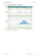
Start Page Design of the User Interface

C

B

E

F

D

A

Figure 24: Design of the user interface's home page (example)

Содержание SI 6.0H-13

Страница 1: ...Operating manual SUNNY ISLAND 4 4M 6 0H 8 0H SI44M 80H 13 BE en 15 Version 1 5 ENGLISH...

Страница 2: ...ot apply in all cases under some statutes and thus the above exclusion may not apply Specifications are subject to change without notice Every attempt has been made to make this document complete accu...

Страница 3: ...ection Area 33 6 3 Inserting the Micro SD Card 34 6 4 Connecting the Grounding Conductor with a Grounded Battery 34 6 5 Connecting the Components 35 6 5 1 Connecting the Battery Fuse to the Sunny Isla...

Страница 4: ...6 6 9 Inserting the Fuse Links in the Fuse Switch Disconnector 67 7 Commissioning 68 7 1 Commissioning Procedure 68 7 2 Commissioning the Inverter 69 7 3 Performing Basic Configuration of the Installa...

Страница 5: ...cedure in the Event of a Generator False Start 100 7 9 Off Grid System 100 7 9 1 Commissioning the Battery Current Sensor in Off Grid Systems 100 7 9 2 Changing the Automatic Frequency Synchronization...

Страница 6: ...sure 127 13 2 Checking the Function 127 13 3 Checking the Connections 127 13 4 Cleaning the Fans 128 13 5 Checking and Maintaining the Battery 130 13 6 Emergency charge mode after automatic shutdown 1...

Страница 7: ...Efficiency Profile 179 16 7 Sunny Island 8 0H Efficiency Profile 180 16 8 Switchover times of the Sunny Island 6 0H 8 0H 180 16 9 Energy Consumption in No Load Operation and Standby or Energy Saving...

Страница 8: ...ted with installing repairing and using electrical devices batteries and installations Training in the installation and commissioning of electrical devices and installations Knowledge of all applicabl...

Страница 9: ...s Elements on a user interface Elements to be selected Elements to be entered Connect the insulated conductors to the terminals X703 1 to X703 6 Enter 10 in the field Minutes Connects several elements...

Страница 10: ...1 8 Additional Information For more information please go to www SMA Solar com Title and information content Type of information List of Approved Batteries Overview of approved batteries Technical In...

Страница 11: ...r Systems with Stand Alone Grid or Increased Self Consumption and Battery Backup Function Detailed system information connection overviews and information on commis sioning System description MULTICLU...

Страница 12: ...he maximum output power of the Sunny Island see Section 16 page 175 The DC terminal of the inverter is exclusively intended for the connection of a battery with external battery fuse Only DC loads or...

Страница 13: ...tric shock in case of overvoltages and if surge protection is missing Overvoltages e g in the event of a flash of lightning can be further conducted into the building and to other connected devices in...

Страница 14: ...order Wear suitable personal protective equipment for all work on the product WARNING Danger to life due to fire or explosion In rare cases an explosive gas mixture can be generated inside the invert...

Страница 15: ...rts in the generator can crush or sever body parts Operate the generator only with the specified safety equipment Carry out all work on the generator in accordance with the manufacturer s specificatio...

Страница 16: ...ure the inverter begins feed in operation during initial commissioning a country data set must be set for instance via the installation assistant on the user interface of the product or via a communic...

Страница 17: ...an apron rubber boots and goggles Rinse acid splashes thoroughly for a long time with clear water and consult a doctor immediately If acid fumes have been inhaled consult a doctor immediately WARNING...

Страница 18: ...he inverter The battery can be damaged by incorrect settings of the battery type nominal voltage and capacity parameters Set the correct battery type as well as the correct values for nominal voltage...

Страница 19: ...e gland M32 B 2 Ventilation grid T 2 Counter nut for cable gland M32 C 1 Wall mounting bracket D 2 Hexagon socket screw M6x10 U 1 Filler plug M20 E 2 Hexagon socket screw M6x16 V 1 Filler plug M25 F 2...

Страница 20: ...ttery temperature sensor optional Communication for Multicluster System Order Option A SI XXXXXX XXX XXXXX XX Sys Can Out Sys Can In B E C D Position Quantity Designation A 1 SI SYSCAN BGx CAN communi...

Страница 21: ...es the inverter You will require the information on the type la bel to use the product safely and when seeking customer support from Service The type la bel must remain permanently attached to the pro...

Страница 22: ...r Alternating current Direct current Transformer The product has a transformer WEEE designation Do not dispose of the product together with the household waste but in accordance with the disposal regu...

Страница 23: ...em structure Generator Utility grid Generator and util ity grid Single system or single cluster sys tem from 3 20 09 R from 3 20 09 R from 3 20 09 R2 Multicluster system with MC Box 12 3 20 from 3 20...

Страница 24: ...r distributing the inverters over several systems If there is an existing Wi Fi or Ethernet connection you can directly access your visualized system via the web browser on your smart device e g smart...

Страница 25: ...nding on the requirements of the grid operator you can activate and configure the functions e g active power limitation via operating parameters 4 5 Control panel with LED signals A B D E F H G C Figu...

Страница 26: ...cluster and multifunction relay 2 in slave 1 of the main cluster are set permanently Furthermore free multifunctional relays can be used for additional functions Possible function or output Explanatio...

Страница 27: ...l conductors of connections X1 to X5 in the automatic transfer switch If the neutral conductor connections are bridged residual current devices could trip accidentally Label the equipment and devices...

Страница 28: ...to children The mounting location must be suitable for the weight and dimensions of the product see Section 16 page 175 The mounting location must not be exposed to direct solar irradiation If the pro...

Страница 29: ...Position of the anchoring points Dimensions in mm Recommended clearances If you maintain the recommended clearances adequate heat dissipation will be ensured Thus you will prevent power reduction due...

Страница 30: ...with installed multicluster data modules at the mounting location planned for master devices Additionally required mounting material not included in the scope of delivery At least two screws that are...

Страница 31: ...or a steel rod diameter maximum 30 mm Keep the Sunny Island in a horizontal position when moving it 8 Use an Allen key AF 5 to attach the Sunny Island to the wall mounting bracket on both sides with...

Страница 32: ...bserved if the optional micro SD card is to be inserted Section 6 4 page 34 For systems with a grounded battery this section must be read and observed Section 6 5 page 35 Information on the connection...

Страница 33: ...on L Enclosure opening for DC C Slot for optional micro SD card M Enclosure opening ExtVtg D BatTmp and BatCur connections N Enclosure opening AC2 E BatVtgOut and DigIn connections O Enclosure opening...

Страница 34: ...Allen key AF 5 and remove the enclosure lid Retain the screws and conical spring washers for later use 2 Insert the micro SD card into the slot up to the stop Do not jam the micro SD card when doing s...

Страница 35: ...d see Section 16 3 page 176 The locally applicable standards and directives must be complied with If a battery fuse is already available no further fuse is necessary Tip Install a battery fuse of the...

Страница 36: ...r can be used lead acid batteries can be used Verify that the battery complies with locally applicable standards and directives and is intrinsically safe Procedure 1 Ensure that the load break switch...

Страница 37: ...en Grid L and the neutral conductor to AC2 Gen Grid NTT see Section 6 6 2 page 57 Thread the grounding conductor through a ferrite included in the scope of delivery and connect to AC2 Gen Grid PE see...

Страница 38: ...3 and X4 N for voltage monitoring to the ExtVtg terminal see Section 6 6 7 page 62 2 At the master connect the tie switch monitoring To do this first connect BatVtgOut with DigIn within the master see...

Страница 39: ...n of Multicluster Box 12 MC Box 12 3 20 6 5 5 1 Connecting the AC Power Cable of the Multicluster Box 12 WARNING Danger to life due to fire In case of a short circuit the short circuit current driven...

Страница 40: ...7 page 62 2 Connect the conductors of X112 3 and X112 4 on the master to ExtVtg on each Sunny Island of the main cluster 3 Connect the conductors of X112 7 and X112 8 on Slave 1 to ExtVtg on each Sun...

Страница 41: ...Sunny Home Manager 2 0 can be directly interconnected via Speedwire If more than 2 devices are to communicate via Speedwire or the Sunny Home Manager 2 0 is to establish an internet connection to the...

Страница 42: ...NC Relay 2 A B NO C NC Relay 1 NO C NC Relay 2 NO C NC Relay 1 NO C NC Relay 2 MASTER SLAVE 1 SLAVE 2 Figure 8 Internal communication cabling example Requirements The total length of the communication...

Страница 43: ...er Box Cable requirements Cable length for BatVtgOut DigIn and BatTemp less than 30 m Procedure Plug the red data cables into the pin connector BackupVtgCur on the Sunny Island units of the main clust...

Страница 44: ...ure Sensor With lead acid batteries the battery management of the Sunny Island inverter must record the temperature of the connected battery Battery temperature sensor in a cluster Only the master mea...

Страница 45: ...ends installing a battery current sensor when connecting DC loads or DC energy sources When connecting DC loads or DC energy sources the SOC calculation can only work correctly with the measured data...

Страница 46: ...unny Island see Section 6 6 6 page 61 6 5 10 Connecting the Control Cable for Autostart Generators Relevant for off grid systems Autostart generators are started and stopped with a contact Signal gene...

Страница 47: ...ay on slave 1 or slave 2 Use the C and NO connections 5 Enter the configuration Automatic generator request in the table of settings see Section 7 10 2 page 102 6 5 11 Connecting a Signaler for Genera...

Страница 48: ...ng Load Shedding Contactors Relevant for off grid systems Load shedding prevents battery deep discharge and controls the supply of energy to the loads Load shedding provides the option of disconnectin...

Страница 49: ...the excess energy Works only in off grid and battery backup systems 1 stage load shedding scheme or first stage in terms of two stage load shedding schemes Load shedding 1 Setting for 1 stage load she...

Страница 50: ...dding contactor Connecting the multifunction relay Relay1 for load shedding 1 Connect the insulated conductor for coil connection A1 of the load shedding contactor on the Sunny Island to terminal Rela...

Страница 51: ...tion in a single system The respective cluster is in operation in a cluster system The Sunny Island is in derating in a single system The respective cluster is in derating in a cluster system Table wi...

Страница 52: ...y management of the Sunny Island inverter is able to control one battery room fan for each battery The following options result for the connection Control a separate battery room fan for each battery...

Страница 53: ...ss section 0 2 mm to 2 5 mm Procedure 1 WARNING Danger to life from electric shock due to incorrect insulation In the case of faulty insulation supposedly de energized parts or cables may be live Touc...

Страница 54: ...he control cable for the utilization of excess energy to the multifunction relay on the Sunny Island 3 Enter the configuration Control of add loads in the table of settings see Section 7 10 2 page 102...

Страница 55: ...battery An incompatible lithium ion battery can lead to a fire or an explosion With incompatible lithium ion batteries it is not ensured that battery management is intrinsically safe and will protect...

Страница 56: ...ables as described in the following 6 Strip off the insulation of the DC cable and mount a terminal lug 7 Route the DC cable on the side of the protective cover marked with a symbol 8 Use an Allen key...

Страница 57: ...nal lug DC connection 14 Ensure that the entire contact surface of the fender washer is in contact with the terminal lug 15 Ensure that the seal insert is positioned correctly in the cable gland 16 Ti...

Страница 58: ...utral conductor to the connection AC2 Gen Grid NTT in battery backup systems Always connect the neutral conductor of the generator to the connection AC2 Gen Grid N in off grid systems CAUTION Danger o...

Страница 59: ...ttery see Section 6 4 page 34 Cable requirements Cross section of the connected line conductor or maximum 16 mm Cable diameters 7 mm to 14 mm Procedure 1 Push the lever of terminal AC1 Loads SunnyBoys...

Страница 60: ...le feed through plate into the enclosure opening of the cable feed through plate and press into the enclosure opening 6 6 5 Connecting Relay 1 and Relay 2 If you are using a multifunction relay always...

Страница 61: ...cable is double insulated 7 Lead the cable into the Sunny Island making sure that it does not touch any data cables 8 Connect the insulated conductors to the 3 pole terminal blocks included in the sco...

Страница 62: ...that the conductors are plugged completely into the terminals up to the insulation 8 In accordance with the labeling plug the 4 pole terminal block into the connection on the inverter until the termin...

Страница 63: ...grounding conductor must be threaded through a ferrite Grounding conductor connection to ground The grounding conductor must be grounded e g by connection to a grounding busbar or a foundation ground...

Страница 64: ...the maximum DC cur rent see technical data of the battery current sensor Checking Connections AC1 and AC2 of the Sunny Island Inverter Test point Test criterion Ok Enclosure openings AC1 and AC2 All...

Страница 65: ...asuring cables are correctly connected see Multi cluster Box manual If installed the measuring cable of the battery current sensor The measuring cable of the battery current sensor is connected to the...

Страница 66: ...ctly connected see the manuals for the devices Ensure by measuring that all system devices are connected with the same ground potential AC1 connection After the system specific connection the required...

Страница 67: ...replacement screw with a serrated conical spring washer 5 On the Sunny Island fasten the enclosure lid following the sequence 1 to 6 using an Allen key AF 5 torque 6 Nm The teeth of the serrated conic...

Страница 68: ...erter The following connection options are available to choose from Direct connection via Wi Fi Section 8 1 1 page 104 Direct connection via Ethernet Section 8 1 3 page 106 Connection via Ethernet in...

Страница 69: ...of the battery fuse must be closed see Section 6 9 page 67 Procedure 1 For systems with 1 Sunny Island press the On button 2 For systems with 3 Sunny Island inverters press and hold the On button on...

Страница 70: ...lect the configuration option Configuration with Installation Assistant The installation assistant will open 2 Follow the installation assistant steps and make the settings appropriate for your system...

Страница 71: ...nitoring Grid monitoring select the parameter Set country standard and set the required country data set 7 5 Changing Thresholds for Systems for Increased Self Consumption Relevant for systems connect...

Страница 72: ...on time recommended by the battery manufacturer 4 Set the parameter Cell charge nominal voltage for boost charge to the cell voltage setpoint recommended by the battery manufacturer for boost charge T...

Страница 73: ...of irrelevant parameters When connecting lithium ion some parameters are displayed in the Battery Charge menu that are not relevant for automatic equalization charge and cannot be set Time for boost...

Страница 74: ...n the season and the hours of sunshine On short days with few hours of sunlight the Sunny Island cannot charge the battery fully Lead acid batteries in particular age faster due to low charging over a...

Страница 75: ...t see Section 7 6 4 1 page 74 When seasonal adjustment is deactivated only the SlfCsmp range is used and the BatRes range increased accordingly The Sunny Island uses the battery for in creased self co...

Страница 76: ...attery When the utility grid is available again the system must be charged manually Battery Ranges of application Lower lmt deep disch protect range prior shutdown The following ranges result from the...

Страница 77: ...ery capacity Minimum width of own consumption range Range for increasing self consumption on the shortest day of the year as a percentage of the battery capacity When seasonal adjustment is deactivate...

Страница 78: ...es its maximum on the longest day This results in the seasonal progression of the ranges t SOC 0 100 A B C D E Winter Summer Winter Figure 18 Ranges of the battery state of charge as a function of the...

Страница 79: ...id Minimum width of backup power range D Deep discharge protection range BatRes Range for protection against deep discharge This range can only be reached when the utility grid fails The Sunny Island...

Страница 80: ...ean grid connection regulations according to Regulation EU 2016 631 are subject shall not be set up as multicluster systems Multicluster systems with battery backup grid can be set up with the Multicl...

Страница 81: ...e Range for increasing self consumption on the shortest day of the year as a percentage of the battery capacity When seasonal adjustment is deactivated this value is used year round for increased self...

Страница 82: ...Res This range can only be reached when the utility grid fails The Sunny Island is switching to energy sav ing mode The Sunny Island starts up every 2 hours and attempts to charge the battery with PV...

Страница 83: ...ich VDE AR N 4105 11 2018 EN50549 1 2018 C10 11 2019 G98 1 2018 G99 1 2018 CEI 0 21 2019 type A type B TOR generator type A of the European grid connection regulations according to Regulation EU 2016...

Страница 84: ...that the Sunny Island does not start up at night preventing it from consuming energy from the battery Level 3 If the state of charge falls below the threshold for level 3 the Sunny Island switches it...

Страница 85: ...nditions In the case of self consumption systems without a battery backup grid this occurs when there is no surplus PV energy available to charge the battery in the state of charge conservation range...

Страница 86: ...ined in another section see Section 8 6 page 113 Relevant for off grid systems The load contactor in the Multicluster Box is a load shedding contactor and is controlled depending on the state of charg...

Страница 87: ...rnal energy source must be able to supply the loads with sufficient power 7 If the off grid system is a multicluster system ensure that the parameter of the multifunction relay is set to Load shedding...

Страница 88: ...parameter Time load shedding 2 and the parameter Start time additional time range load shedding 2 each to the same value e g to 00 00 00 This will switch the time dependent load shedding off 6 Ensure...

Страница 89: ...t the parameter Lmt value battery state of charge for start load shedding 1 to the lower SOC threshold for the standard time period 4 Set the parameter Lmt value battery state of charge for stop load...

Страница 90: ...or for the second level of load shedding The load shedding contactor connects those loads to the utility grid that were disconnected for the second level When the state of charge of the battery reache...

Страница 91: ...ce Load shedding 2 5 Set the parameter Limit battery state of charge for start load shedding 2 in add time range to the lower SOC threshold for the second stage of load shedding 6 Set the parameter Li...

Страница 92: ...difference relative to the setpoint of the cell voltage during the constant voltage phase 3 Recording of the measured values of the cell voltage reacts to changes with time lag The Sunny Island calcu...

Страница 93: ...age 3 Set the parameter Voltage monit gener upper maximum threshold to the maximum generator voltage 7 8 1 3 Changing the Frequency Thresholds of the Generator Voltage Relevant for off grid systems Th...

Страница 94: ...es with increasing torque If the speed of rotation decreases the frequency of the generator voltage is reduced If the frequency of the generator voltage falls below the rated frequency the generator m...

Страница 95: ...p time is set too low the generator management terminates the generator start before the internal warm up time has expired Procedure 1 Select Generator Operation 2 For a generator without internal war...

Страница 96: ...tic generator start to Enable 7 8 4 2 Changing a State Of Charge Dependent Generator Request Relevant for off grid systems If the battery reaches the lower SOC threshold the generator management reque...

Страница 97: ...e time dependent generator request apply From 10 00 p m to 6 00 a m the generator is not to start where possible t SOC 30 40 80 6 a m 10 p m 12 a m Standard time period Additional time period Figure 2...

Страница 98: ...lectric discharging and cycling and extends its service life The performance of the off grid system for supplying loads increases to the sum of the generator power and the power of the Sunny Island in...

Страница 99: ...ng on the start date The start date determines the weekday Procedure 1 Select Generator Time controlled generator operation 2 Set the parameter Time controlled generator operation to Enable 3 Set the...

Страница 100: ...the maximum value the Sunny Island switches into error status The Sunny Island attempts to restart the generator upon expiry of the Idle period after generator fault Single cluster systems The genera...

Страница 101: ...Battery Battery fuse 3 Close the battery fuse load break switch quickly and switch on the Sunny Island 4 Set the parameter Current sensor type 60mV 50mV to the type and amplification factor of the bat...

Страница 102: ...frequency synchronization set the parameter Automatic frequency control to Disable 3 To activate automatic frequency synchronization set the parameter Automatic frequency control to Enable 7 10 Multi...

Страница 103: ...y SOH will deviate strongly from the actual values of SOC and SOH for a newly connected battery During operation the values recorded by battery management will gradually approach the real values In th...

Страница 104: ...letion of the first 10 operating hours or of the installation assistant You can request the SMA Grid Guard code via the Online Service Center SSID IP address and WLAN password SSID in WLAN SMA serial...

Страница 105: ...password see WPA2 PSK on the type label of the product or the rear side of the manual included in delivery 4 Open the web browser of your smart end device and enter http smalogin net in the address ba...

Страница 106: ...t does not have an iOS operating system for importing and exporting files Procedure Enter the IP address of the product in the address bar of the web browser The login page of the user interface opens...

Страница 107: ...ant A smart device e g smartphone tablet or laptop must be available The smart device must be in the same local network as the product The respective latest version of one of the following web browser...

Страница 108: ...password for the user group Installer via the user interface of the inverter the same password must also be used as the system password Assign a uniform installer password to all SMA devices in the s...

Страница 109: ...8 Operation SMA Solar Technology AG Operating manual 109 SI44M 80H 13 BE en 15 8 3 Start Page Design of the User Interface C B E F D A Figure 24 Design of the user interface s home page example...

Страница 110: ...played Device configuration Various settings for the inverter can be made here The selection available is dependent on which user group you are logged in as and the operating system of the device with...

Страница 111: ...w much the PV system fed in Power at the grid connection point Indicates which power is currently fed in or obtained at the grid connection point MC status system Status of the multicluster system MC...

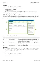
Страница 112: ...Layout of the installation assistant example Position Designation Description A Configuration steps Overview of the installation assistant steps The number of steps de pends on the type of device and...

Страница 113: ...turer documentation Parameter names and units depend on the inverter s firmware version The parameter names and units depend on the inverter s firmware version Parameter names and units of inverters w...

Страница 114: ...me 7 Select the Repetition cycle for time controlled inverter operation Repetition parameter and set it to the required repetition cycle Time controlled inverter operation is set 8 To activate time co...

Страница 115: ...To switch on the WLAN connection in the local network in the parameter group System communication WLAN select the parameter WLAN is turned on and set this to Yes 8 10 Configuring the Energy Meter You...

Страница 116: ...a PV system via Modbus the dynamic active power limitation of the PV inverters must be deactivated Procedure Activate the Modbus interface and adjust the communication ports if necessary see the tech...

Страница 117: ...run every Monday from 07 00 a m to 08 00 a m Set the generator as follows Time controlled generator operation Yes activation of the function Start time for time controlled generator op 2015 01 05 Mon...

Страница 118: ...verter is glowing orange and the Sunny Island inverters are in standby mode 9 2 Starting the System Start inverter via user interface Starting the inverter via the user interface is an alternative to...

Страница 119: ...utton To stop the inverter via the user interface set Device parameters Device Operation General operating mode to Stop Procedure 1 For systems with 1 Sunny Island press the start stop button on the S...

Страница 120: ...iggers the uncontrolled shutdown of the system and unsaved data is lost Only trip the emergency disconnection to avoid danger or consequential damage In the event of an emergency disconnection in a mu...

Страница 121: ...es select the menu Events 4 To call up instantaneous values select the menu Data 5 Follow the instructions in the user interface 10 2 Exporting Event Messages With this function you can save the event...

Страница 122: ...uster the master carries out the firmware update on the slaves In a multicluster system each master requires its own firmware update In a single cluster system carry out the firmware update on the mas...

Страница 123: ...the context menu select Saving the configuration in a file 6 Follow the instructions in the dialog 10 7 Adopting a Configuration from a File To configure the inverter you can adopt the configuration...

Страница 124: ...tops the generator 11 2 Stopping the Generator via the User Interface WARNING Risk of crushing injuries due to movable generator parts A generator can be started automatically by the Sunny Island Movi...

Страница 125: ...nd Sunny Island After the warm up period the Sunny Island connects the stand alone grid to the generator 11 4 Stopping the Generator without Autostart Function 1 Stop the generator via the user interf...

Страница 126: ...the load break switch in the battery fuse and secure against reconnection 7 Wait 15 minutes This enables electric discharge of the capacitors in the inverter 8 NOTICE Destruction of the Sunny Island i...

Страница 127: ...he desired time period and select Apply time filter 6 If error messages have been logged eliminate the cause see Section 14 2 page 140 13 3 Checking the Connections DANGER Danger to life due to electr...

Страница 128: ...for the left hand side and rechts right for the right hand side Cleaning the Fans Proceed as follows to clean each fan DANGER Danger to life due to electric shock when live components or cables are t...

Страница 129: ...er the fan is soiled 10 If the fan is dirty clean the fan as described below 11 Push the front locking tabs of the fan backwards and the rear locking tabs of the fan forwards 12 Slowly remove the fan...

Страница 130: ...ctor immediately If acid fumes have been inhaled consult a doctor immediately WARNING Danger to life due to burns caused by electric arcs through short circuit currents Short circuit currents in the b...

Страница 131: ...s see manual of battery manufacturer 5 In the case of lead acid batteries measure the voltages of the individual cells and log the results see manual of battery manufacturer 6 Perform and log the test...

Страница 132: ...on of the battery manufacturer Procedure Connect the generator with connection AC1 Adjust the system configuration for the emergency charge mode not required for single phase off grid system Charge th...

Страница 133: ...generator 15 Enter the nominal current of the generator connected under Nominal current 16 Select Save and next for each step up to the step Summary 17 Once all settings are correct select Next in the...

Страница 134: ...Section 8 2 page 107 4 Transfer the original system configuration from the saved file see Section 10 7 page 123 Starting the System 1 Start the system see Section 9 2 page 118 2 Connect the circuit b...

Страница 135: ...ct the battery environment from open flames embers and sparks Install operate and maintain the battery in accordance with the manufacturer s specifications Do not burn the battery and do not heat it b...

Страница 136: ...rocedure 1 Stop the system and switch off the Sunny Island see Section 9 page 118 2 Ensure that the battery is not grounded unintentionally 3 If the battery is unintentionally grounded identify the co...

Страница 137: ...duct NOTICE Damage to the inverter due to electrostatic discharge Touching electronic components can cause damage to or destroy the inverter through electrostatic discharge Ground yourself before touc...

Страница 138: ...eals can be damaged Moisture can penetrate the product and damage it Only open the product if the ambient temperature is not below 5 C If a layer of ice has formed on the enclosure seal when temperatu...

Страница 139: ...t proceed as follows Requirements All circuit breakers in the AC distribution board must be open All Sunny Island inverters must be connected correctly see Section 6 7 page 63 All inverters must be cl...

Страница 140: ...of autostarts is restricted When the maximum number of autostarts has been reached the Sunny Island reacts as follows The Sunny Island waits ten minutes The autostart counter is reset The Sunny Islan...

Страница 141: ...the Service 301 Rise in voltage protection Rise in voltage protection of line conductor Lxx Corrective measures Ensure that the conductor cross section of the AC cables is correctly sized 405 External...

Страница 142: ...ve measures for utility grid Contact the Service 803 Grid incident The voltage and or frequency of the generator or the utility grid is are outside of the config ured range Corrective measures for gen...

Страница 143: ...or Lxx disconnects from the external energy source be cause the ratio of AC voltage and battery voltage is too high Either the voltage at connec tion AC2 is too high or the battery voltage too low Cor...

Страница 144: ...t The feed in current at line conductor Lxx is higher than the set maximum value parameter Maximum current from utility grid Corrective measures Contact the Service 1411 Grid incident The external cur...

Страница 145: ...t the tie switch is correctly wired Ensure that the feedback contact is correctly connected 1416 Grid incident The Sunny Island system disconnects from the generator or utility grid due to a power imb...

Страница 146: ...time for the generator is set to a sufficient duration To re enable connection of the generator acknowledge the error 1616 Synchronization not executed Synchronization with the generator not successfu...

Страница 147: ...nd Find the cause of the overvoltage through measurement and step by step connection of the AC sources and loads 1708 Stand alone grid An overfrequency has occurred at connection AC1 of the Sunny Isla...

Страница 148: ...nny Island An external energy source e g generator may have been connected to the connection AC1 Disconnect external energy source from connection AC1 and connect to connection AC2 1712 Stand alone gr...

Страница 149: ...rresponding Sunny Island of the main cluster is correctly inserted When doing so observe the correct sequence of the Multicluster Box connections to the Sunny Island inverters see the Multicluster Box...

Страница 150: ...relay of the Sunny Island at line conductor Lxx Corrective measures Reduce the total power of the loads e g by staggering their use over time Connect the loads with very high power directly to the gen...

Страница 151: ...2 7003 7004 Fan sensor error permanently on There is a short circuit or cable break at a temperature sensor of the device at line conductor Lxx Corrective measures Contact the Service 7010 Short circu...

Страница 152: ...rameter again For grid relevant parameter Ensure that the SMA Grid Guard code is available 7106 Update file defective The update file is defective The update failed Corrective measures Update the firm...

Страница 153: ...tions of the update file used for the inverter settings are not fulfilled Corrective measures Retry update Ensure that the selected update file is suitable for this inverter If this message is display...

Страница 154: ...e configuration file is not of the required format or is damaged Corrective measures Ensure that the selected configuration file is of the required format and is not damaged Retry import 7349 Incorrec...

Страница 155: ...he Service 7601 Communication impaired Communication error IPC There is an error in the inverter Corrective measures Contact the Service 7602 Communication failure Device internal CAN communication is...

Страница 156: ...7616 Communication failure Device internal communication of the device at Lxx is disturbed Corrective measures Contact the Service 7617 Communication with MC BOX interrupted Communication with Multic...

Страница 157: ...ee energy meter manual Establish connection between the inverter and the DHCP server router via Ethernet 7716 Section switch does not open Tie switch does not open Corrective measures Ensure that the...

Страница 158: ...a fault status cluster is stopped Corrective measures Read off the pending and logged warnings and errors and eliminate the causes Contact the Service 8610 8611 Error in the cluster configuration The...

Страница 159: ...voltage supply of contactor Q10 Q110 of the Multicluster Box to fail Corrective measures Eliminate the short circuit 8617 Extension clusters have a country data set configured that is different to tha...

Страница 160: ...ched 9313 Battery error The lower limit of the temperature range approved by the battery manufacturer has been un dercut Corrective measures Ensure that the ambient conditions of the battery manufactu...

Страница 161: ...measures Check whether the value set for the parameter Battery voltage is above 65 0 V If the value is above 65 0 V check the settings of the DC sources and ensure that the battery capacity is suffici...

Страница 162: ...ve measures Check whether the grid parameters is still within the set system limits Contact the grid operator if necessary 9397 Equalization charge interrupted The equalization charge for lithium ion...

Страница 163: ...14 No time information could be called up from the set NTP server Corrective measures Ensure that the NTP server was configured correctly Ensure that the inverter is integrated into a local network wi...

Страница 164: ...ork cable and the network connector are not damaged and that the network connectors are correctly plugged Ensure that the DHCP server router and any network switches are signalizing correct operation...

Страница 165: ...e Wi Fi password and the encryption method have been entered correctly The encryption method is specified by your Wi Fi router or Wi Fi access point and can be changed there Ensure that the Wi Fi rout...

Страница 166: ...d or discharged depending on the purchased electricity or the grid feed in 10421 Self consumption control was stopped The automatic charging or discharging of the battery stopped due to an external co...

Страница 167: ...les for troubleshooting Service requires these files in order to provide you with the necessary assistance Requirement The menu Events must be open on the user interface Procedure 1 Carry out the corr...

Страница 168: ...C sources in the stand alone grid e g sufficient solar irradiation for PV inverters switch the Sunny Island on AC sources in the stand alone grid can start feeding in electric current only once the Su...

Страница 169: ...8 page 135 Why is the SOC of the battery not 100 after completion of full charge The power requirements of the loads might have been so high before completion of the full charge that the battery could...

Страница 170: ...com If the voltage and frequency of the generator are not within the thresholds set ensure that the fuse is not defective or that the circuit breaker is switched on If the voltage and frequency of the...

Страница 171: ...e parameters Inverter nominal voltage and Inverter nominal frequency to the same value for all masters The battery capacities might differ significantly Distribute the battery capacities to the cluste...

Страница 172: ...nged via operating parameters Contact the Service and change IGMP settings in consultation with the Service department 14 8 Set time for detection of communication failure If communication between the...

Страница 173: ...15 minutes until the capacitors have discharged Observe all safety information on components associated with the product Wear suitable personal protective equipment for all work on the product CAUTIO...

Страница 174: ...ter horizontally 8 Regarding SI6 0H 13 and SI8 0H 13 Remove the inverter by lifting it vertically up and off the wall mounting bracket For this use the side recess grips or a steel rod diameter maximu...

Страница 175: ...Hz to 65 Hz 45 Hz to 65 Hz Frequency range of the set range 10 Hz 10 Hz 10 Hz Rated Current 14 5 A 20 0 A 26 1 A Maximum output current as a peak value for 60 mil liseconds 60 A 120 A 120 A Total harm...

Страница 176: ...apparent power grid operation mode 3 3 kVA 4 6 kVA 6 0 kVA18 Displacement power factor cos 0 8 to 0 8 0 8 to 0 8 0 8 to 0 8 Maximum AC input current off grid system 50 A 50 A 50 A Maximum inrush curr...

Страница 177: ...or lead acid bat teries C10 per 1000 Wp output of the PV system in off grid systems 100 Ah 100 Ah 100 Ah Minimum capacity recommended for lithium ion bat teries C10 per 1000 Wp output of the PV system...

Страница 178: ...SI6 0H 13 SI8 0H 13 Maximum efficiency 95 3 95 8 95 8 European weighted efficiency 94 0 94 3 94 1 16 5 Sunny Island 4 4M Efficiency Profile 86 88 90 92 94 96 98 SI4 4M 13 0 0 4 1 0 0 8 0 2 0 6 Output...

Страница 179: ...ng manual 179 SI44M 80H 13 BE en 15 16 6 Sunny Island 6 0H Efficiency Profile 86 88 90 92 94 96 98 SI6 0H 13 0 0 4 1 0 0 8 0 2 0 6 Output power Rated power Efficency V 42 V DC BAT V 48 V DC BAT V 54 V...

Страница 180: ...impedance switching21 0 ms Switchover time of the inverter for low impedance switching21 20 ms 16 9 Energy Consumption in No Load Operation and Standby or Energy Saving Mode SI4 4M 13 SI6 0H 13 SI8 0...

Страница 181: ...nd response Communication via Modbus interface Export limiting in accordance with AS NZS 4777 2 EDMM 10 EMETER 20 HM 20 Demand Response Mode DRM0 16 13 Equipment Number of buttons 3 Number of LEDs 3 t...

Страница 182: ...ter each error 1 file per error For 50 errors For 50 errors 16 15 DC Load Limitation Curve of the Multifunction Relays Figure 30 DC load limitation curve of multifunction relays 1 and 2 16 16 General...

Страница 183: ...E en 15 SI4 4M 13 SI6 0H 12 SI8 0H 13 Climatic category in accordance with IEC 60721 3K6 3K6 Degree of protection in accordance with IEC 60529 IP54 IP54 Radio technology WLAN 802 11 b g n WLAN 802 11...

Страница 184: ...or your product in the following overview If required these can be ordered from SMA Solar Technology AG or your distributor Designation Brief description SMA order number SI SYSCAN BGx Communication i...

Страница 185: ...ce Battery inverter Device type Serial number Firmware version Event message File with event messages for troubleshooting Service files for troubleshooting Type and size of additional energy sources T...

Страница 186: ...3 EU 22 5 2014 L 153 62 RED Restriction of the use of certain hazardous substances 2011 65 EU L 174 88 June 8 2011 and 2015 863 EU L 137 10 March 31 2015 RoHS SMA Solar Technology AG confirms herewith...

Страница 187: ...egulations 2017 SI 2017 1206 The Restriction of the Use of Certain Hazardous Substances in Electrical and Electronic Equipment Regulations 2012 SI 2012 3032 SMA Solar Technology AG confirms herewith t...

Страница 188: ...www SMA Solar com...

Отзывы: