8 Commissioning
SMA Solar Technology AG
44
REDUCERBOX-BA-en-16
User Manual
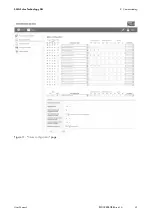
8.3.5 Setting General System Statuses
1. Log in as "
Installer
".
2. Select "
Status configuration
" in the context menu.
3. In the "
Failure tolerance time
" field, enter the desired failure tolerance time from when an invalid
input signal is recognised as an error. In practice, an invalid input status may be present for a
short time during a status change, e.g. if two relays activate simultaneously for 1 s. The failure
tolerance time should be set to long enough that no error message is generated during this
transition of statuses.
4. In the "
Debounce time
" field, enter the desired debouncing delay. The value states how long a
signal must be present at a minimum of one input port in order for it to be recognised as such
and subsequently processed by the system. This setting prevents short impulses that are caused
by mechanical contact bounces being falsely recognised as a signal during the status transition.
5. In the "
Time interval in case of changed setting
" field, enter the time interval in seconds during
which the control command should be sent to the registered Sunny WebBoxes once the setpoint
of the ripple control receiver has changed. Once the setpoint has been reached,
the Power Reducer Box switches to the status "
Time interval in case of constant setting
".
Example: if 60 seconds is entered, the Power Reducer Box would transmit a control command
to the registered Sunny WebBoxes every 60 seconds with the changed setpoint value.
6. In the "
Time interval in case of constant setting
" field, select the factor by which the value of the
"
Time interval in case of changed setting
" should be multiplied. The "
Time interval in case of
constant setting
" specifies the cycle in which the control command shall be sent to the
Sunny WebBoxes if the setpoint of the ripple control receiver is reached.
7. In the "
Maximum change in case of power increase
" field, enter the maximum percentage
change per minute after lifting an active power limitation (requirement for reconnecting plants
to the 20 kV electricity grid: max. 10% of the connected active power per minute.)* .
8. In the "
Maximum change in case of power decrease
" field, enter the maximum percentage
change per minute after a request for an active power limitation.
9. In the "
Reference parameter
" field, enter the reference parameter for the inverters. The reference
parameter specifies to which value the active power limitation will refer. Ensure that your
connected inverters support the set reference parameter (see "
Compatibility list
").
10. Select [
Save
].
☑ The configurations are saved.
* Technical directive "Generating plants connected to the medium-voltage network", BDEW (German Association of Energy and
Water Industries), June 2008
Содержание POWER REDUCER BOX
Страница 2: ......
Страница 41: ...SMA Solar Technology AG 8 Commissioning User Manual REDUCERBOX BA en 16 41 Figure 11 Status configuration page...
Страница 77: ......
Страница 78: ......

