starts to energise the grid. During grid connection, the
inverter measures the continuous leakage current in the
system. If this level is exceeded more than 4 times during
24 hours, the inverter stops operating due to safety
hazards in the PV system.
NOTICE
Depending on the local legislation, a minimum earth-to-
PV isolation resistance is defined. A typical value is
82 kΩ.
Self-test
The insulation resistance between the PV arrays and earth
is also tested during the self-test. The inverter does not
energise the grid if the resistance is too low. It then waits
10 minutes before making a new attempt to energise the
grid.
Residual current
Residual current is continuously monitored. The inverter
ceases to energise the grid when:
•
The cycle RMS value of the residual current
violates the trip settings for more than the
duration of ‘clearance time’, or
•
A sudden jump in the residual current is detected
Grid Surveillance
Grid-related parameters are under constant surveillance
when the inverter energises the grid. The following is
monitored:
•
Grid voltage magnitude (instantaneous and 10
minute average)
•
Grid voltage and frequency
•
Loss of Mains (Islanding detection):
•
3-phase Loss of Mains (LoM) detection
•
Rate of Change of Frequency (ROCOF)
•
Frequency shift.
•
DC content of grid current
•
Residual current by means of RCMU
The inverter ceases to energise the grid if one of the
parameters violates the grid code.
2.3.3 Operation Modes
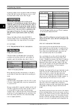
The inverter has 5 operation modes, indicated by LEDs.
Status
LEDs
Off grid
Green
- - - - - - - - - - - - - - - - -
Red
- - - - - - - - - - - - - - - - -
Connecting
Green
▬
██
▬
██
▬
██
▬
██
▬
██
▬
Red
- - - - - - - - - - - - - - - - -
On grid
Green
▬
██████████████████
▬
Red
- - - - - - - - - - - - - - - - -
Internal inverter event
Green
▬
██
▬
██
▬
██
▬
██
▬
██
▬
Red
- - - - - - - - - - - - - - - - -
Fail safe
Green
- - - - - - - - - - - - - - - - -
Red
▬
██
▬
██
▬
██
▬
██
▬
██
▬
Table 2.1
Off grid (standby)
(LEDs off)
#0-51.
When no power has been delivered to the AC grid for
more than 10 minutes, the inverter disconnects from the
grid and shuts down. User and communication interfaces
remain powered for communication purposes.
Connecting
(Green LED flashing)
#52-53.
The inverter starts up when the PV input voltage reaches
the minimum DC feed-in voltage. The inverter performs a
series of internal self-tests, including measurement of the
resistance between the PV arrays and earth. Meanwhile, it
also monitors the grid parameters. When the grid
parameters have been within the specifications for the
required amount of time (depends on grid code), the
inverter starts to energise the grid.
On grid
(Green LED on)
#60.
The inverter is connected to the grid and energises the
grid. The inverter disconnects when:
•
it detects abnormal grid conditions (dependent
on grid code), or
•
an internal event occurs, or
•
PV power is insufficient (no power is supplied to
the grid for 10 minutes)
The inverter then enters connecting mode or off grid
mode.
Internal Inverter Event
(Green LED flashing)
#54
The inverter is waiting for an internal condition to become
within limits (for example a too high temperature) before
it will go back on grid.
Fail Safe
(Red LED flashing)
#70.
If the inverter detects an error in its circuits during the self-
test (in connecting mode) or during operation, the inverter
goes into fail safe mode, disconnecting from grid. The
Inverter Overview
L00410648-02_02 / Rev. date: 2014-10-03
9
2
2


