

SMA Solar Technology AG
6 Electrical Connection
Operating Manual
MC-BOX-12-3-20-BE-en-10
21
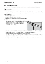
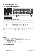
6.5 Connecting the Loads
The line conductors
L1
,
L2
and
L3
are routed via a fuse switch-disconnector in the Multicluster Box. The maximum
permitted 200 A LV/HRC size 1 fuse links are installed in the fuse switch-disconnector by default.
Cable requirements:
Conductor material: copper
Conductor cross-section: 120 mm² to 150 mm²
The power cables must be ground-fault and short-circuit protected.
Procedure:
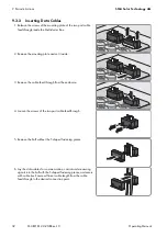
1. Insert the power cables into the Multicluster Box (see Section 9.3.1, page 31).
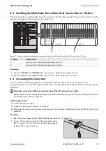
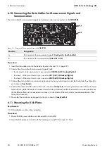
2. Connect the grounding conductor to the grounding busbar
(AF 17, torque: 15 Nm). To do this, use the screw terminal
included in the scope of delivery.
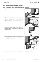
3. Connect the neutral conductor to the spring-cage terminal
N
at terminal
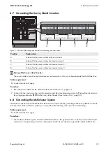
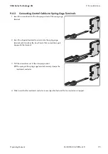
4. Connect the line conductors to the spring-cage terminals
L1
,
L2
and
L3
at terminal
X103:1-3
.
5. Ensure that a right-hand rotating magnetic field is present at the load terminal.
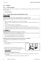
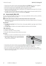
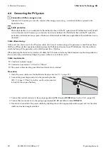
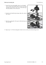
6. Provide for strain relief of the power cables by attaching them to the appropriate cable support rail. Use the strain
reliefs and counter-troughs provided.
7. According to the type of cable routing and the installation conditions, determine the required fuse link for the fuse
switch-disconnector and insert it into the fuse switch-disconnector
Load
.
Cable Protection
The Multicluster Box is not a substitute for the load distribution board. Between the Multicluster Box and the loads,
you must install a distribution board with circuit breakers to protect and isolate the loads, as well as a residual-current
device. Make sure all standards and directives applicable at the installation site are observed.