Page
1
of
21
SlingStick
Instructions
Страница 1: ...Page 1 of 21 SlingStick Instructions ...
Страница 2: ...of 21 Thank you for selecting the SlingStick Table of Contents WARNINGS 3 SAFETY PRECAUTIONS 3 SET UP 4 CHANGING TO LOCKED MODE 6 CHANGING OR REPLACING THE POWER BAND 8 REPLACING THE FOOT PAD 17 CONTACT US 21 ...
Страница 3: ... Commission CPSC and does not interfere with your movement vision or hearing when riding For your safety do not SlingBoard if you are pregnant The SlingStick should always remain out to your side at least one foot out from the edge of the SlingBoard Keep the SlingStick out that distance from the SlingBoard to minimize any chance of it hitting the board or wheels which could cause an abrupt stop an...
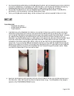
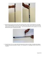
Страница 4: ...wo sided bolt that was in the parts bag with these instructions All parts are displayed and labeled in the Parts Diagram and List at the back of these instructions for your reference Lay the SlingStick down on a soft surface and separate the two sides of the Post Bolt Next locate the center hole in the SlingStick just below the decal Slowly slide the chrome inside tube outward from the black outsi...
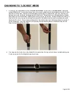
Страница 5: ...es then slide it back in Next align the screw holes and insert the screws back into those holes Tighten the screws back in with the screwdriver until snug 5 To change your SlingStick to the LOCKED mode you will need to insert the included Detent Pin Keep your Detent Pin with you while you SlingBoarding to enable this option to do that you may simply keep it in your pocket or secure it to the Sling...
Страница 6: ...ing the outside tube down over the inside tube watching the locking hole as you do this Hold the Detent Pin with your free hand and once you see the locking hole aligned in the inside tube through the outside tube push the Detent Pin into it Those holes will align when the outside tube has compressed down to expose 1 of the inside tube Push the Detent Pin completely through the SlingStick so that ...
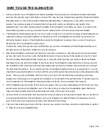
Страница 7: ...ement push it in hard then start pulling the SlingStick back toward you in a smooth stroke just like you would in Stand Up Paddle Boarding Once you get to the middle of the stroke where the SlingStick is aligned with your side you can let the SlingStick do the work from there and stop pulling then just let your forward momentum take you through the back half of the stroke As you do this lean into ...
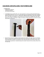
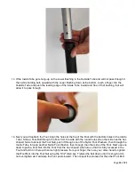
Страница 8: ...on each side of the SlingStick Remove both of those screws with a Phillips head screw driver Note how the handle is positioned in relation to the decal on side aligned with it or turned Then slide the handle out to remove it 2 Next locate the four 4 Foot Bolts securing the foot to the bottom of the Inside Tube Use the 5 32 Allen key to back the Foot Bolts out of the Foot Nuts on the other side of ...
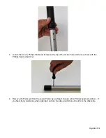
Страница 9: ...1 3 Remove the Post Bolt in the center hole of the SlingStick with a flat head screwdriver 4 Carefully turn the SlingStick over covering the top with one hand and let the Inside Tube slide out of the Outside Tube ...
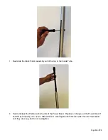
Страница 10: ...f the Inside Tube and remove them with the Phillips head screwdriver 6 Remove the Piston pin from the Lower Piston by pushing it through with a Phillips head screwdriver If you feel strong resistance when pushing it out turn the tube around to push out from the other side ...
Страница 11: ...he top of the Inside Tube 8 Hand unthread the Pistons at both ends of the Power Band Replace or change out the Power Band if needed by threading on a new or different band Hand tighten both Pistons onto the new Powerband until they are snug but do not overtighten ...
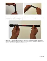
Страница 12: ...mall hole in the side of the Upper Piston If it is not unthread the Lower Piston just enough to align 10 Next go back to the Inside Tube and identify the top end that is the end with only two small holes in it the bottom end where the foot attaches has four larger holes Slide the piston assembly down into the top end of the Inside Tube inserting the Lower Piston first ...
Страница 13: ...he Piston Pin back into the Lower Piston with a Phillips head screwdriver If you feel strong resistance when pushing it in turn the tube around to push it in from the other side 12 Push the Piston Pin in to center it best from side to side in the Lower Piston Hold the tube sideways so that you may see how well it is centered You may push it in or out slightly to further center it once in position ...
Страница 14: ...ead Screws back into the two holes at the top of the Inside Tube one goes in on each side locking the Upper Piston back into place inside 14 Next slide the Inside Tube back down into the Outside Tube by inserting the bottom end of the Inside Tube into the top end of the Outside Tube ...
Страница 15: ...the Foot from the side with the round holes the other side has the hex shaped holes to accept the Foot Nut push it through one of the Nylon Foot Washers then through the Inside Tube through another Nylon Foot Washer then through the other side of the Foot Next use one hand to push a Foot Nut into the Foot from the hex shaped side hole so that it is fully recessed in the Foot and hold it in there w...
Страница 16: ...ecal on the side Then turn it slightly if needed to align the holes in it with those at the top of the Outside Tube Next insert the two Phillips Flat Head screws back into the Handle through the holes at the top of the Outside Tube 18 Finally replace the Post Bolt back into the center hole of the SlingStick just below the decal The Power Band has now been replaced or changed ...
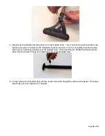
Страница 17: ...AD Tools Required 5 32 Allen Key Included 1 Locate the six 6 Foot Bolts around the sides of the Foot and back them out with the 5 32 Allen Key Each Foot Bolt will have a Foot Bolt Washer on it set all of these parts aside for reassembly ...
Страница 18: ...ront edge of the Foot is aligned with the arrow pointing to the front of the Pad 4 Set both down on a flat hard surface then push the Foot firmly down into the pad then give it a firm press down on all four sides to ensure that it is well seated 5 Finally replace the six 6 Foot Bolts by threading them back in with the 5 32 Allen key around all four sides of the Pad The Foot Pad has now been replac...
Страница 19: ...Page 19 of 21 PARTS DIAGRAMS ...
Страница 20: ... gets installed 1 High power band in bag is included in box Low power band 10 Latex SSPBL10 High power band 6 Latex SSPBH6 Lower Piston 1 x 3 Injection molded plastic cylinder SSLP1 Piston Pin 1 x 1 Injection molded plastic rectangular block SSPP1 Inside Tube 1 x 51 Aluminum tube with channel cut chrome finish SSIT1 Foot Bushing 1 x 1 Injection molded plastic cylinder SSFB1 ...
Страница 21: ...x 7 Velcro Loop Tie SSVT1 Hardware Handle Upper Piston Screws 4 x SS 6 Flat head Phillips drive screws SS 6S3 4 Post Bolt 1 Included in bag x SS 1 3 8 Two sided bolt SSSB1 Detent Pin 1 Included in bag x SS 1 Pin with ring SSDP1 Foot Bolts 2 x SS 10x24 2 hex drive bolts SSFBT1 Foot Nuts 2 x SS 10x24 SSFN1 Foot Bolt Nylon Washers 4 x 5 8 OD Nylon Washers Black SSFW1 Pad Bolts 6 x SS 10x24 hex drive ...