background image

ISSUED: 11-30-09   SHEET #: 202-9417-1

©

UL

US

C

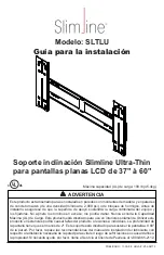
Slimline Ultra-Thin Tilt Mount  

for 37" to 60" LCD Flat Panel Screens

Max UL Load Capacity: 100 lb (45.4 kg)

Model: SLTLU

Installation Guide

This product was designed to be installed on wood stud walls and solid concrete (2000 psi density 
minimum) or cinder block walls. Before installing make sure the supporting surface will support the 
combined load of the equipment and hardware. Screws must be tightly secured. Do not overtighten screws 
or damage can occur or product may fail. Never exceed the Maximum UL Load Capacity. This product 
is intended for indoor use only. Use of this product outdoors could lead to product failure or personal 
injury. Depth of screen must be less than 2". This mount is designed to attach the screen 0.68" from the 
wall. Please refer to manufacturer's installation guide recommendations for required distance from wall 
to avoid risk of injury or property damage. For support please call customer care at 1-800-865-2112.

WARNING

Содержание SLTLU

Страница 1: ...oftheequipmentandhardware Screwsmustbetightlysecured Donotovertightenscrews or damage can occur or product may fail Never exceed the Maximum UL Load Capacity This product is intended for indoor use only Use of this product outdoors could lead to product failure or personal injury Depth of screen must be less than 2 This mount is designed to attach the screen 0 68 from the wall Please refer to manu...

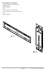
Страница 2: ...2 of 52 ISSUED 11 30 09 SHEET 202 9417 1 A 1 B 2 Tools Needed for Assembly recommended phillips screwdriver drill level hammer optional ...

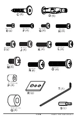
Страница 3: ...02 9417 1 C 6 E 6 M4 x 12 mm D 6 F 4 M4 x 25 mm G 4 M5 x 12 mm H 4 M5 x 25 mm I 4 M6 x 12 mm J 4 M6 x 20 mm K 4 M6 x 25 mm L 4 M6 x 30 mm M 6 M8 x 16 mm N 4 M8 x 25 mm O 4 M8 x 40 mm T 1 P 4 ID 219 5 56 mm Q 4 ID 344 8 74 mm R 6 S 1 ...

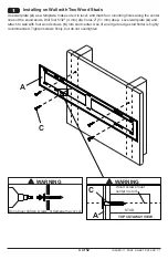
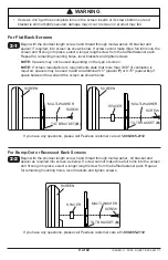
Страница 4: ...Studs 1 Use wall plate A as a template make sure it is level and mark four mounting holes along the center A and attach to wall with four wood screws C A C Do not over tighten screws or damage may occur WARNING C A TOP CUTAWAY VIEW Wood screws must center in stud STUD WARNING ...

Страница 5: ...d Studs 1 Use wall plate A as a template make sure it is level and mark six mounting holes along the center A and attach to wall with six wood screws C C A Do not over tighten screws or damage may occur WARNING C A TOP CUTAWAY VIEW Wood screws must center in stud STUD WARNING ...

Страница 6: ...6 of 52 ISSUED 11 30 09 SHEET 202 9417 1 Installing to Solid Concrete or Cinder Block 1 Level wall plate A A D into holes and secure wall plate A with six screws C C A D SOLID CONCRETE CINDER BLOCK ...

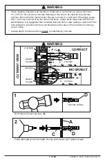
Страница 7: ...into mortar joints Be sure to mount in a solid part of the block gener ally 1 25 mm minimum from the side of the block Cinder block must meet ASTM C 90 A hole instead of a hammer drill to avoid breaking out the back of the hole when entering a void or cavity Y directly to load bearing concrete WARNING CUTAWAY VIEW INCORRECT CORRECT drywall wall plate wall plate concrete concrete drywall WARNING ...

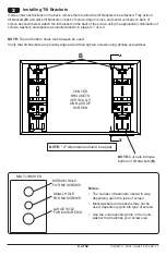
Страница 8: ...ate combination of screws washers and spacers as required shown in steps 2 1 or 2 2 NOTE Top and bottom holes must always be used Verify that tilt brackets are properly aligned and then tighten screws using phillips screwdriver 2 X X B CENTER BRACKETS VERTICALLY ON BACK OF SCREEN NOTE X dimensions should be equal NOTE Cut outs indicate bottom of tilt brackets B Notes depending upon the type of scr...

Страница 9: ... additional 0 5 spacer P or 0 75 spacer Q of space between the wall and the screen as shown below Begin with the shortest length screw hand thread through multi washer tilt bracket and spacer as required into screen as below If screw cannot make three full turns into the screen _ for remaining mounting holes level brackets and tighten screws If you have any questions please call Peerless customer ...

Страница 10: ...10 of 52 ISSUED 11 30 09 SHEET 202 9417 1 Mounting the Flat Panel Screen 3 Fully extend tilt brackets B and move tilt brackets toward wall plate A _ Y _ DETAIL 1 FLANGES B B B A ...

Страница 11: ...T to lock down safety latches securing tilt brackets to wall plate as shown in detail 2 Reverse steps 3 and 4 to remove screen DETAIL 2 SAFETY LATCH WALL PLATE SAFETY SCREW B 4 Failure to lock brackets B with safety screws can cause sceen to come off mount if hit accidentally WARNING ...

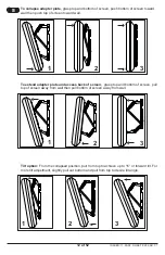
Страница 12: ...ward wall 1 3 2 1 2 3 1 3 2 Tilt option From the collapsed position pull from top to achieve up to 15 of forward tilt For more tilt adjustment slightly pull out bottom and pull from top to desire tilt angle To extend adapter plate and access back of screen grasp top and bottom of screen pull top of screen away from wall then pull bottom of screen away from wall ...

Страница 13: ... UL de Carga Este producto está diseñado para uso en interiores solamente Utilizar este producto en exteriores podría causar fallas del producto o lesiones a individuos La profundidad de la pantalla tiene que ser menos de 2 Este soporte está diseñado para sostener la pantalla a 0 68 de la pared Por favor repase las recomendaciones del manual de instalación del fabricante con respecto a la distanci...

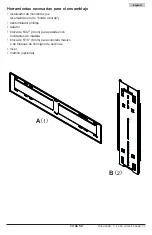
Страница 14: ...14 de 52 PUBLICADO 11 30 09 HOJA 202 9417 1 Español Herramientas necesarias para el ensamblaje recomienda uno de borde a borde montantes de madera o de bloques de hormigón de escorias A 1 B 2 ...

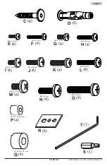
Страница 15: ... 9417 1 Español C 6 E 6 M4 x 12 mm D 6 F 4 M4 x 25 mm G 4 M5 x 12 mm H 4 M5 x 25 mm I 4 M6 x 12 mm J 4 M6 x 20 mm K 4 M6 x 25 mm L 4 M6 x 30 mm M 6 M8 x 16 mm N 4 M8 x 25 mm O 4 M8 x 40 mm T 1 P 4 ID 219 5 56 mm Q 4 ID 344 8 74 mm R 6 S 1 ...

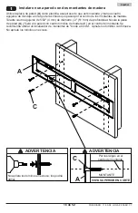
Страница 16: ...que esté nivelada y marque cautro agujeros de montaje a lo largo de las líneas que pasan por el centro de los montantes de madera de pared A y fíjela a la pared con cautro tornillos de madera C en el centro del montante Se Y No apriete los tornillos en exceso Pernos largos en el centro del montante C A dañar ADVERTENCIA ADVERTENCIA VISTA SUPERIOR EN CORTE MONTANTE ...

Страница 17: ...lo largo de las líneas que pasan por el centro de los montantes de madera Taladre seis A y fíjela a la pared con seis tornillos de madera C en el centro del montante Se recomienda utilizar un Y en exceso Instalar en una pared con tres montantes de madera C A Pernos largos en el centro del montante C A dañar ADVERTENCIA ADVERTENCIA VISTA SUPERIOR EN CORTE MONTANTE ...

Страница 18: ...añol 1 Instalar en una pared de concreto Nivele la placa de pared A y úsela como plantilla para marcar cautro agujeros de montaje Taladre A anclajes D A a la pared con seis pernos largos C Apriete C A D CONCRETO MACIZO BLOQUE DE HORMIGÓN DE ESCORIAS ...

Страница 19: ... taladre en juntas de argamasa Asegúrese de hacer la instalación en la parte sólida del bloque por lo general a un mínimo de 1 25 mm del extremo del bloque Los bloques de hormigón de Y Q taladro eléctrico convencional a baja velocidad para hacer el agujero en vez de un taladro percutor para no perforar el fondo del agujero al entrar en un vacío o una cavidad ADVERTENCIA INCORRECTO CORRECTO placa d...

Страница 20: ...sarios como se muestra en el paso 2 1 o en el paso 2 2 NOTA Siempre se tienen que usar los agujeros superiores y los inferiores usando un destornillador phillips 2 X X B CENTRE LOS SOPORTES VERTICALMENTE EN LA PARTE TRASERA DE LA PANTALLA NOTA Las dimensiones X deben ser iguales NOTA Los extremos recorta dos indican la parte inferior de los soportes inclinables B Notas según el tipo de pantalla ar...

Страница 21: ...espaciador Q más de espacio entre la pared y la pantalla como se muestra abajo 2 1 Si tiene alguna pregunta por favor llame a servicio al cliente de Peerless al 1 800 865 2112 PANTALLA ARANDELA MÚLTIPLE TORNILLO SOPORTE INCLINABLE B SOPORTE INCLINABLE B TORNILLO PANTALLA ESPACIADOR Instalación de un televisor que tiene la parte posterior abultada o empotrada Comience con uno de los tornillos más c...

Страница 22: ...oportes inclinables B totalmente y mueva los soportes inclinables hacia la placa de pared A pestañas dea placa de pared como se muestra en el detalle 1 Siempre cuente con un asistente o con un equipo mecánico de izar para levantar y colocar los televisores de pantalla plana con más seguridad DETALLE 1 PESTAÑAS B B B A ...

Страница 23: ...e seguridad con una llave allen T paso 3 y 4 para quitar la pantalla DETALLE 2 SEGURO FIJADOR PLACA DE PARED B TORNILLOS DE SEGURIDAD Si no asegura el soporte de gancho B con el tornillo de seguridad la pantalla sepuede salir del montaje si se golpea accidentalmente ADVERTENCIA ...

Страница 24: ... posición se derrumbó tire de la parte superior de la pan talla para conseguir 15 de la inclinación Para más el ajuste de inclinación tirar ligeramente de la parte inferior de la pantalla y tire de la parte superior para al ángulo deseado Para extender la placa adaptadora y alcanzar la parte trasera de la pantalla agarre la retirarla de la pared y luego tire de la parte inferior de la pantalla par...

Страница 25: ...allation assurez vous que la surface de support peut soutenir sans danger la charge totale de l équipement peut endommager les composants et en réduire considérablement la capacité de support Ne dépassez jamais la capacité de charge maximale UL Ce produit est conçu uniquement pour un usage intérieur L utilisation de ce produit à l extérieur peut causer une défaillance du produit ou des blessures c...

Страница 26: ...26 sur 52 Français PUBLIÉ LE 11 30 09 FEUILLE no 202 9417 1 Outils nécessaires au montage montants bord à bord est recommandé J à montants en bois à béton plein et block de béton A 1 B 2 ...

Страница 27: ...UILLE no 202 9417 1 C 6 E 6 M4 x 12 mm D 6 F 4 M4 x 25 mm G 4 M5 x 12 mm H 4 M5 x 25 mm I 4 M6 x 12 mm J 4 M6 x 20 mm K 4 M6 x 25 mm L 4 M6 x 30 mm M 6 M8 x 16 mm N 4 M8 x 25 mm O 4 M8 x 40 mm T 1 P 4 ID 219 5 56 mm Q 4 ID 344 8 74 mm R 6 S 1 ...

Страница 28: ... à ce qu elle soit de niveau et marquez le centre J A à niveau Q C au centre du montant L usage d un localisateur de montants bord à bord est fortement conseillé Serrez fermement les vis Ne pas trop serrer A C Ne pas trop serrer les vis cela pourrait endommager le support DESSIN ÉCLATÉ VU DU HAUT Vis à bois au centre du montant MONTANT C A ADVERTISSEMENT ADVERTISSEMENT ...

Страница 29: ...re J po 4 mm de dia et de 2 po 51 mm de profondeur Mettez la plaque murale A Q au mur à l aide de six vis à bois C au centre du montant L usage d un localisateur de montants bord à bord est fortement conseillé Serrez fermement les vis Ne pas trop serrer C A Ne pas trop serrer les vis cela pourrait endommager le support DESSIN ÉCLATÉ VU DU HAUT Vis à bois au centre du montant MONTANT C A ADVERTISSE...

Страница 30: ...z la plaque murale A à niveau et utilisez la comme gabarit pour marquer l emplacement des J A D A au mur à l aide de six longs boulons C Serrez fermement les vis Ne pas trop serrer Installation sur béton plein ou bloc de parpaing 1 C A D BÉTON PLEIN BLOC DE PARPAING ...

Страница 31: ...ncrages de béton Ne percez pas dans les joints de mortier Veillez à effectuer le montage dans une partie pleine du bloc généralement à au moins 25 mm 1 po du côté Y Q Pour percer le trou il est conseillé d utiliser une perceuse électrique standard sur un réglage vous pénétrez un vide ou une cavité ADVERTISSEMENT INCORRECT CORRECT plaque mural béton VUE EN COUPE sèche plaque mural béton ADVERTISSEM...

Страница 32: ...emarque Les trous supérieurs et inférieurs doivent toujours être utilisés Veillez à ce que les supports inclinables soient bien alignés puis serrez les vis à l aide d un tournevis phillips 2 X X B CENTREZ LES SUPPORTS À LA VERTICALE À L ARRIÈRE DE L ÉCRAN REMARQUE les dimensions de X doivent être égales REMARQUE Les fentes indiquent le bas des supports inclinables B Remarques varie suivant le type...

Страница 33: ...E B ENTRETOISE Commencez par la vis la plus courte et vissez la manuellement à l écran en la faisant passer à travers la rondelle le support inclinable et l entretoise comme indiqué ci dessous S il est REMARQUE Il n est pas toujours nécessaire d utiliser des entretoises selon le type d écran REMARQUE Si les exigences de montage du fabricant de l écran indiquent qu il est néces saire de réserver un...

Страница 34: ...ètement les supports inclinables B et dirigez les vers la plaque murale A comme Y plaque murale comme illustré dans le dessin de détail 1 Pour lever et positionner l écran plat en toute sécurité faites vous toujours aider par une autre personne ou utilisez un dispositif de levage mécanique DÉTAIL 1 BRIDES B B B A ...

Страница 35: ...té des supports inclinables à la plaque murale comme illustré dans le dessin de détail 2 Inverser l étape 3 et 4 pour supprimer l écran DÉTAIL 2 VERROU DE SÉCURITÉ PLAQUE MURALE B 4 DE SÉCURITÉ Vissez bien le support à crochets B àl aide de la vis de sécurité sinon le moniteur pourrait tomber de sa monture s il était frappé acciden tellement ADVERTISSEMENT ...

Страница 36: ... 2 1 2 3 1 3 2 Tilt option Á partir de la position repliée tirez le haut de l écran pour obtenir 15 d inclinaison Pour plus de l inclinaison tirez légèrement sur fond et tirez le haut de l écran pour obtenir désiré d inclinaison Pour allonger la plaque d adaptation et avoir accès à l arrière de l écran tenez ferme ment l écran par le haut et par le bas et tirez le haut de l écran hors du mur puis ...

Страница 37: ...rehen können die Schrauben beschädigt werden wodurch ihr Haltevermögen stark reduziert wird Die maximale Tragfähigkeit UL darf niemals überschritten werden Dieses Produkt ist nur für den Gebrauch innerhalb von Gebäuden bestimmt Eine Verwendung dieses Produkts im Freien kann zu Produktausfall oder Personenschaden führen Die Bildschirmtiefe muss kleiner als 51 mm 2 Zoll sein Dieser Halter ist für di...

Страница 38: ...Deutsch 38 von 52 AUSGEGEBEN 11 30 09 BLATT NR 202 9417 1 Kantenanzeige empfohlen Porenbetonstein G A 1 B 2 ...

Страница 39: ...LATT NR 202 9417 1 C 6 E 6 M4 x 12 mm D 6 F 4 M4 x 25 mm G 4 M5 x 12 mm H 4 M5 x 25 mm I 4 M6 x 12 mm J 4 M6 x 20 mm K 4 M6 x 25 mm L 4 M6 x 30 mm M 6 M8 x 16 mm N 4 M8 x 25 mm O 4 M8 x 40 mm T 1 P 4 ID 219 5 56 mm Q 4 ID 344 8 74 mm R 6 S 1 ...

Страница 40: ...r Montagebohrungen entlang der Mittellinien der Holzständer 2 Zoll Richten Sie die Wandplatte A waagerecht aus und bringen Sie sie mit vier langen Schrauben C G Y genauer Kantenanzeige Ziehen Sie die Schrauben fest an ohne sie zu überdrehen 1 A C Ziehen Sie die Schrauben nicht zu fest an damit es nicht zu Beschädigungen kommt ACHTUNG SCHNITTANSICHT VON OBEN Lange Schrauben in Mitte des Ständers HO...

Страница 41: ...hs Montagebohrungen entlang der Mittellinien der von 51 mm 2 Zoll Richten Sie die Wandplatte A waagerecht aus und bringen Sie sie mit sechs langen Schrauben C G Y mit genauer Kantenanzeige Ziehen Sie die Schrauben fest an ohne sie zu überdrehen C A Ziehen Sie die Schrauben nicht zu fest an damit es nicht zu Beschädigungen kommt ACHTUNG SCHNITTANSICHT VON OBEN Lange Schrauben in Mitte des Ständers ...

Страница 42: ...ne um sechs Montagebohrungen zu markieren Bohren Sie sechs Löcher mit einem Durchmesser von 8 mm D in die Bohrungen ein und bringen Sie die Wandplatte A mit vier langen Schrauben C an der Wand an Ziehen Sie die Schrauben fest an ohne sie zu überdrehen Installation zu massivbeton oder porenbetonstein 1 C A D MASSIVBETON PORENBETONSTEIN ...

Страница 43: ...ür die Betondübel ge Y Sie darauf dass die Anbringung an einem massiven Teil des Blocks erfolgt im Allgemeinen mindestens 25 mm 1 Zoll von der Blockseite entfernt Die Porenbetonsteine müssen den Y Q Q G anstelle eines Schlagbohrers einen standardmäßigen Elektrobohrer bei niedriger Einstellung zu verwenden um zu verhindern dass die Bohrungsrückseite beim Eintritt in einen Leer oder Hohlraum ausbric...

Страница 44: ...beren und unteren Bohrungen verwendet werden Achten Sie darauf dass alle Kipphalterungen korrekt ausgerichtet sind und ziehen Sie dann die Schrauben mit einem Kreuzschlitzschraubendreher an 2 HINWEIS Die X Abstände müssen identisch sein X X B Zentrum Klammern senkrecht auf der Rückseite des Bildschirms HINWEISS Die Ausschnitte geben die Unterseite der Kipphalterungen B an HINWEISE Die Anzahl der S...

Страница 45: ...unten dargestellt mit Hilfe von Abstandhaltern um weitere 13 mm 0 5 Zoll Abstandhalter P oder 19 mm 0 75 Zoll Abstandhalter Q vergrößert werden 2 1 BILDSCHIRM ABSTAND HALTER MULTISCHEIBE SCHRAUBE KIPPHALTERUNG B SCREEN MULTISCHEIBE SCHRAUBE KIPPHALTERUNG B Beginnen Sie mit der kürzesten Schraube und schrauben Sie diese wie unten dargestellt von Hand nach Bedarf durch die Multischeibe die Kipphalte...

Страница 46: ...nd schieben Sie sie wie in Abbildung 3 1 dargestellt zur Wandplatte A hin Haken Sie die Kipphalterungen in beide Flansche der Wandplatte ein wie in Detailansicht 1 dargestellt Ziehen Sie immer eine zusätzliche Person heran oder verwenden Sie mechanische Hebegeräte um den Flachbildschirm sicher zu heben und zu positionieren B B B A Detailansicht 1 ...

Страница 47: ...halterungen sicher an der Wandplatte zu befestigen siehe Detailansicht 2 Zum Abnehmen des Bildschirms wird Schritte 3 und 4 in umgekehrter Reihenfolge durchgeführt Detailansicht 2 B 4 WANDPLATTE SICHERHEITSVER RIEGELUNG SICHERHEIT SCHRAUBE Wenn die Halterung B nicht mit den Sicherheitsschrauben gesichert wird kann der Bildschirm bei versehentlichem Anstoßen vom Halter herabfallen ACHTUNG ...

Страница 48: ...ie in der zusammengeschobenen Stellung an der Oberseite um den Bildschirm bis maximal 15 nach vorne zu neigen wie in Detailansicht 5 dargestellt Eine weitere Neigungseinstellung ist möglich wenn Sie die Unterseite leicht herausziehen und an der Oberseite ziehen bis der gewünschte Neigungswinkel erzielt ist 1 3 2 1 2 3 1 3 2 fassen Sie den Bildschirm am oberen und unteren Rand und ziehen zuerst die...

Страница 49: ...ce or repairs by Peerless Industries Inc b the failure to utilize proper packing when returning the product c incorrect installation or the failure to follow Peerless instructions or warnings when installing using or storing the product or d misuse or accident in transit or otherwise including in cases of third party actions and force majeure In no event shall Peerless be liable for incidental or ...

Страница 50: ...una vigencia limitada al período de garantía Y La presente garantía no abarca los daños causados por a trabajos de servicio mantenimiento o reparación hechos por el cliente o una persona que no está autorizada por Peerless Industries Inc para realizar esos trabajos b no utilizar un embalaje apropiado al devolver el producto c una instalación incorrecta o no seguir las instrucciones o advertencias ...

Страница 51: ...les réparations effectuées par le client ou par une personne non agréée par Peerless Industries Inc b la non utilisation de l emballage approprié lors du renvoi du produit c une installation incorrecte ou le non respect des instructions ou des avertissements de Peerless lors de l installation de l utilisation ou du rangement du produit ou d une mauvaise utilisation ou un accident pendant le transp...

Страница 52: ...ung von geeigneter Verpackung bei der Rücksendung des Produkts c falsche Installation oder Nichtbefolgung bzw Nichtbeachtung von Peerless Anweisungen oder Warnhinweisen bei der Installation Verwendung oder Lagerung des Produkts oder d Missbrauch oder Unfall während des Transports oder anderweitig einschließlich Handlungen Dritter und höherer Gewalt Auf keinen Fall haftet Peerless für Neben oder Fo...

Отзывы: