Made in Norway
© Sleipner Motor AS 2006
®
SLEIPNER MOTOR AS
P.O. Box 519
N-1612 Fredrikstad
Norway
Tel: +47 69 30 00 60
Fax: +47 69 30 00 70
w w w. s i d e - p o w e r. c o m
[email protected]
Keep this
manual onboard !
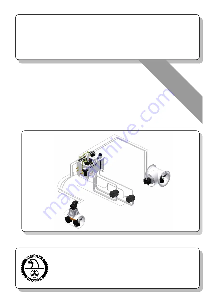
Hydraulic
system
Installation, start-up, user
and service manual
SIDE-
POWER


