21
10
Installation of your equipment
10.1 Mounting
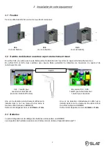
The housing has to be mount on a wall as represented below ::
10.2 Wall remover detection switches
A screw on the wall have to be install in the
housing hole indicate in ANNEX to detect a tear
down.
This screw must extend out of the wall by 55mm
+/-1mm
A screw on the wall have to be install in the
housing hole indicate in ANNEX to detect a tear
down.
This screw must extend out of the wall by 24mm +/-
1mm
10.3 Battery
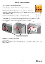
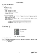
Batteries integration drawing and wiring schematics are available in APPENDIX.
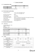
*Capacities of batteries to be associated are listed in Table Capacity Battery §9.11.
C38
(4 screws)
C85
(4 screws)
C24
(3 screws)
C24 switch – C38 – C85 switch
C24: 1 switch for both
housing tamper and
housing snatch
C38 – C 85: 1 switch for
housing tamper and a
switch for housing snatch
Содержание AXS3
Страница 14: ...14...
Страница 28: ...28...
Страница 43: ...43 COFFRET CABINET GEH USE C85 12V 86Ah 12V 65Ah 24V 38Ah 24V 24Ah 26Ah...
Страница 47: ...47...

