background image

Assembly Instructions

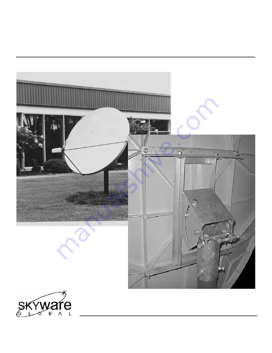
Type 180 Antenna System

1.8 Meter Reflector with Az/El Cap Mount

8000352-03

Skyware Global

1315 Industrial Park Drive

Smithfield, NC  27577

Telephone:

  +1-919-934-9711

 
Internet:

 www.skywareglobal.com

Printed in U.S.A. 

05/13  8000352-03 Rev D EC-01728

Содержание 180

Страница 1: ...Antenna System 1 8 Meter Reflector with Az El Cap Mount 8000352 03 Skyware Global 1315 Industrial Park Drive Smithfield NC 27577 Telephone 1 919 934 9711 Internet www skywareglobal com Printed in U S A 05 13 8000352 03 Rev D EC 01728 ...

Страница 2: ... or nonconformances caused by improper shipping handling or storage and v have not been installed operated or maintained in accordance with Seller s instructions Buyer shall present any claims along with the defective VSAT product s to Seller immediately upon failure Non compliance with any part of this warranty procedure may invalidate this warranty in whole or in part SELLER MAKES NO WARRANTY EX...

Страница 3: ...eck Bolt ITEM 17 M12 x 25 mm Round Head Square Neck Bolt ITEM 38 M6 x 20 mm Round Head Square Neck Screw ITEM 26 M6 x 20 mm Hex Head Cap Screw ITEM 31 M6 x 30 mm Hex Head Cap Screw Note Hardware illustrations are actual size Place hardware on top of illustration to identify Shipping cartons should be unpacked and contents checked for damaged or missing parts Should there be any parts that are dama...

Страница 4: ...ndation design refer to Antenna Wind loads in Appen dix A on page 14 Before Roof Mount installation it must be determined that the roof used for mounting the antenna is structurally sound If in doubt have it checked by an architect or structural engineer It is the customer s responsibility that proper construction techniques and applicable codes are adhered to As with any other type of constructio...

Страница 5: ... 5 in O D C Minimum Diameter Below Frost Line Approx 51 mm 2 in 1676 mm 66 in See Note 3 rebar x 46 m 18 9 5 rebar x 457 mm Insert through hole in tube and center 3 R e b a r 6 3 rebar x 6 m 24 in 9 5 x 610 mm at 60 apart See note 51 mm 2 in Bubble Level Ground Pole Must Be Vertical in All Directions at Top NOTE 127 cm 50 may be increased to frost line Concrete and length of rebar will increase ac...

Страница 6: ...orque to 20 ft lbs 27 N m IMPORTANT For correct orientation of antenna the UP arrow must be as shown in Figure 1 1 and Figure 1 2 After M12 x 100mm antenna bolts are torqued then torque top bottom angle bolts 17 and hex nuts 3 to 38 ft lbs 51 N m 5 NOTE 10mm tools fit M6 hardware Recommendations for Site Selection Assembly Tools Required for Assembly a Pre Installation Checklist and a Hardware Sor...

Страница 7: ...hten Insert one side feed leg 30 into junction block 29 and secure with M6 x 30mm hex bolt and flat washer 31 and 32 Do not tighten Insert bottom feed leg 33 into junction block 29 until lance on leg is engaged Insert opposite side feed leg 30 into junction block 29 and secure with M6 x 30mm hex bolt and flat washer 31 and 32 IMPORTANT Tighten and torque hardware securing side feed legs and bottom...

Страница 8: ...ine the values for your earth station antenna site L is the difference between the earth station antenna site longitude and the satellite longitude Use L and your earth station latitude to obtain polarization elevation or azimuth setting Elevation Alignment Refer to Chart 1 to determine your elevation setting IMPORTANT Before adjustment loosen the two bolts 13 18 on each side of this housing 1 2 t...

Страница 9: ...G FEED CABLES Ground Wire NEC Section 810 20 Ground Block NEC Section 810 20 Coaxial Cables To Receiver Coaxial Cables From LNB GROUNDING FEED CABLES GROUNDING 8 ALL INSTALLATIONS TO CONFORM TO THE LATEST ISSUE OF THE NATIONAL ELECTRIC CODE Ground pole antenna mount assembly and feed cables must be grounded in accordance with current National Elec Code and local electric codes to protect from surg...

Страница 10: ...ATOR FEED ROTATION Facing Antenna For Polarization Rotate Counter Clockwise For Polarization Rotate Clockwise Antenna Polarization Chart Sign Values or Northern Hemisphere Southern Hemisphere Antenna Site West of Satellite Longitude Antenna Site East of Satellite Longitude Feed ...

Страница 11: ...Determine the difference between your site longitude and the satellite longitude n Find you latitude on horizontal axis n Follow your latitude up until you intersect the curve for your n Read Elevation value on vertical axis ELEVATION IN DEGREES ...

Страница 12: ...ATELLITE LONGITUDE EARTH STATION ANTENNA AZIMUTH IN DEGREES EARTH STATION ANTENNA AZIMUTH IN DEGREES EARTH STATION ANTENNA LATITUDE IN DEGREES NORTH OR SOUTH OF EQUATOR AZIMUTH COLUMN READING WHEN EARTH STATION IS WEST OF SATELLITE AZIMUTH COLUMN READING WHEN EARTH STATION IS EAST OF SATELLITE AZIMUTH CHART ...

Страница 13: ...T M12 1 12 SWIVEL NUT M12 1 1 PARTS AND HARDWARE 1 2 3 14 13 18 2 8 17 6 7 2 3 20 8 2 3 2 3 6 9 8 10 11 4 12 3 2 8 18 3 3 19 24 16 23 22 15 2 18 21 FIG 3 0 AZ EL CAP NO DESCRIPTION QTY 13 HEX HD BOLT M12 x 25mm 1 14 LABEL ELEVATION 1 15 HEX HD BOLT M12 x 30mm 4 16 CANISTER WELDMENT 1 17 RD HD SQ NK BOLT M12 x 25mm 4 18 RD HD SQ NK BOLT M12 x 35mm 7 19 FLAT WASHER LARGE 2 20 SPRING PIN M8 X 20mm 1 ...

Страница 14: ...13 PARTS HARDWARE ...

Страница 15: ...1 1cm 59 5in 183 8cm 72 4in 22 6 O 12 6 O L C M E C H A X IS B E A M A X IS L C POLE HORIZONTAL ANTENNA 8 9cm 3 5in 31 0cm 12 2in 10 0 O L C POLE 64 0cm 25 2in 114 3mm 4 5in O D Type 180 1 8m Antenna System with AZ EL Cap Mount NOTES Dimensions shown are for ground pole 4 50 D D Schedule 40 Fy 50KSI or 4 Pipe SCH 80 Fy 36KSI 4 5 O D x 3 83 I D Purchased locally METRIC GROUND POLE DIMENSIONS 114 3m...

Страница 16: ...43 1677 710 984 7 756 30 53 1519 1008 892 7 025 40 63 1337 1215 756 6 184 50 73 1166 1337 635 5 393 60 83 972 1398 491 4 496 70 93 729 1082 378 3 372 Mo BASED ON 55 5 FROM MOUNTING SURFACE TO C OF ANTENNA kg Pounds x 45359 N m Foot Lbs x 1 35582 Values shown above represent maximum forces for any wind direction Height and exposure factors from the uniform building code are NOT included FIG 4 0 ...

Страница 17: ...tor Check intergrity of bolts securing reflector to back structure or az el mount Tighten any loose hardware Check for signs of damage such as cracking Inspect reflector face for impact damage Check hardware for signs of corrosion repair or replace as needed 4 Feed Support Structure Check for loose hardware tighten if necessary Check for signs of structural damage such as bending Check hardware an...

Отзывы: