TM
Page 16
December 2007
DC Electric Full-size RTs
Component Identification
Section 2 - Operation
2.5 Component Identification
The following descriptions are for identification,
explanation and locating purposes only.
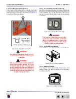
2.5-1 Battery Connectors
The battery connectors are located at the front of the
pull-out battery tray.
2
1
Figure 2-1. Battery Connectors
Battery Connectors
1.
- These connectors, when
separated, disconnect the batteries and all power
to the platform and base controls. In the event of
an emergency or when performing maintenance,
grasp the handle and pull the connectors apart.
Battery Lockout
2.
- This lockout is provided to
prevent unauthorized use of the aerial platform
and for maintenance purposes.
2.5-2 Motion Alarm
The alarm produces an audible sound when any control
function is selected. On aerial platforms with certain
options, a flashing amber light will accompany this
alarm.
2.5-3 Tilt Alarm
The aerial platform is equipped with a device which
senses when the aerial platform is out of level in any
direction. When activated, it disables drive and lift
functions of the aerial platform and an alarm produces
an audible sound accompanied by the amber light. If
the alarm sounds, lower the platform completely, then
reposition aerial platform so that it is level before raising
the platform.
NOTE
If the tilt alarm sounds and the platform does
not, or only partially raises, immediately
lower the platform completely and ensure
that the aerial platform is on a firm
level
surface.
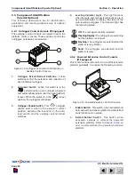
2.5-4 Electrical Panel
This panel is located in the hydraulic/electric cabinet. It
contains the following controls:
2
1
Figure 2-2. Electrical Panel
Circuit Breakers
1.
- In the event of a power overload
or positive circuit grounding, the circuit breaker
pops out. Push breaker back in to reset.
Hourmeter
2.
- This gauge records accumulated
operating time of the arial platform.
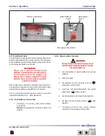
2.5-5 Base Control Console
The control console is located outside the electrical/
hydraulic compartment. It contains the following
controls:
1
2
3
Figure 2-3. Base Control Console
1.
Base/Platform Switch - This switch allows the
operator to activate either the “
” base or
“
” platform controls.
2.
Platform Raise/Lower Switch - This switch
controls “
” raising or “
” lowering of
platform.
3.
Emergency Stop Button - This button “
”, when
depressed, disconnects power to control circuit.


