1
GRAVITA’
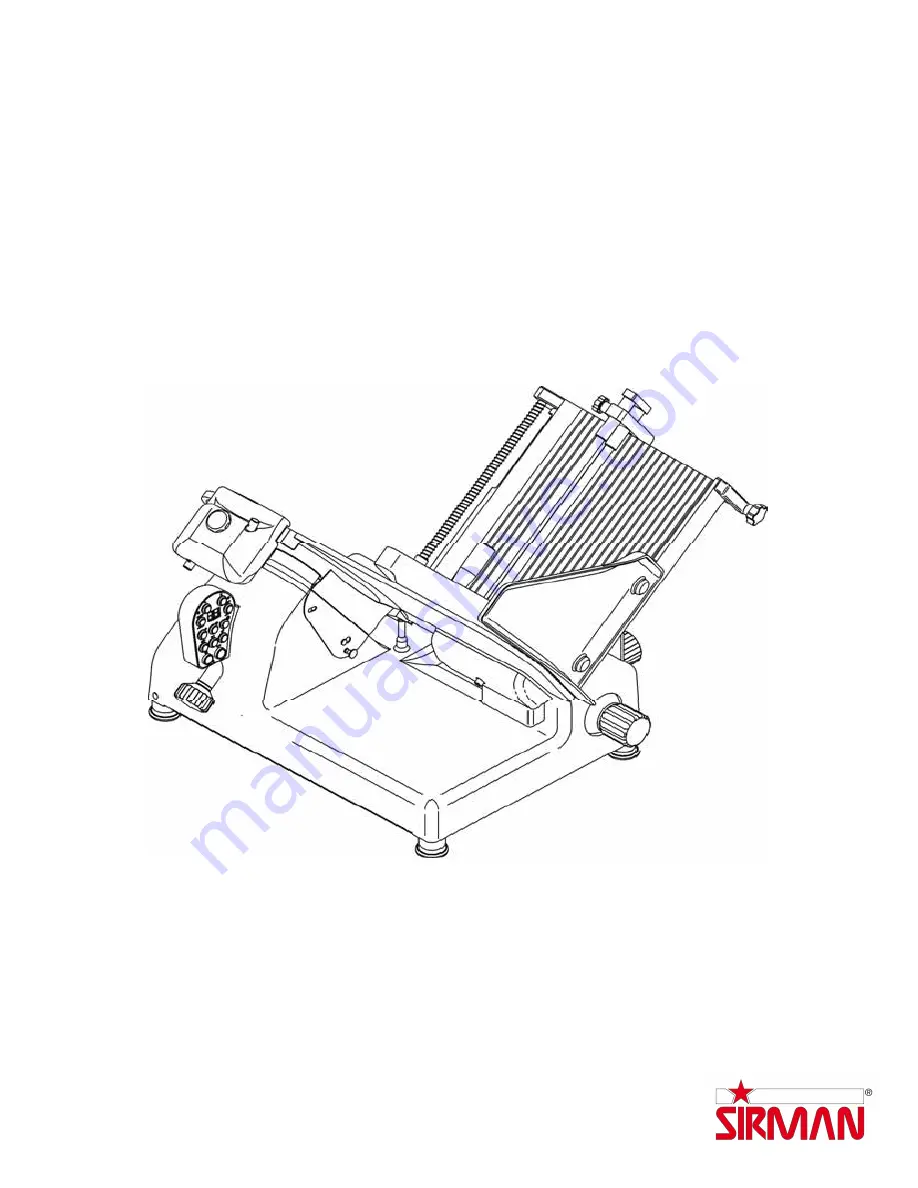
PLL 300-330-350 AUTOMATICA
EC Professional Slicer
U
SE
AND
MAINTENANCE
MANUAL
Страница 1: ...1 GRAVITA PLL 300 330 350 AUTOMATICA EC Professional Slicer USE AND MAINTENANCE MANUAL ...
Страница 2: ...POSITIONING 2 3 ELECTRICAL CONNECTION 2 3 1 Slicer with single phase motor 2 3 2 Slicer with 400 V three phase motor 2 3 3 Slicer with 230 V three phase motor 2 3 4 Blade rotation direction 2 4 WIRING DIAGRAM 2 5 CONTROL PANEL 2 6 PRELIMINARY CHECK CHAP 3 INFORMATION ON THE MACHINE page 11 3 1 GENERAL SAFETY PRECAUTIONS CHAP 4 GETTING FAMILIAR WITH THE SLICER page 13 4 1 CONSTRUCTION FEATURES 4 2 ...
Страница 3: ... the greaseguard 6 2 4 Cleaning the sharpener 6 3 SLIDE GUIDES LUBRICATION CHAP 7 MAINTENANCE page 26 7 1 FOREWORD 7 2 BELT 7 3 FEET 7 4 FEEDING CABLE 7 5 BLADE 7 6 GRINDERS 7 7 SLIDE GUIDES LUBRICATION 7 8 PUSH BUTTON PANEL LABEL 7 9 ERROR CODES CHAP 8 DISMANTLING page 28 8 1 PUTTING THE MACHINE OUT OF SERVICE 8 2 SCRAPPING 8 3 WEEE Waste of Electric and Electronic Equipment ...
Страница 4: ...ctive nylon Packaging materials must be disposed of separately and in conformity with waste treatment legislation of the country of destination Dimensions AxBxC Gross weight Kg PLL 300 780x640x700 46 PLL 330 780x640x700 47 PLL 350 780x640x700 48 Do not stack more than one machine on top of another Fig n 3 WARNING B A C Fig n 1 Fig n 2 Fig n 3 ...
Страница 5: ...re are no 1 2 CHECKING PACKAGING UPON DELIVERY Heavyweight package Do not manually lift without the help of at least three people Fig n 5 To handle and move the package use suitable manual or electric material handling equipment fitted with suitable lifting accessories Fig n 6 Do not expose the package to humidity or rain Fig n 4 As the centre of gravity of the package is off centre do not to use ...
Страница 6: ...dboard box h The package should contain a machine on pallet Fig n 11 detail a b blade extractor Fig n 11 detail e c 4 feet Fig n 11 detail f d toolkit case Fig n 11 detail b Check that the following items are inside the toolkit case Fig n 11 1 Instruction booklet detail d 2 CE compliance certificate detail c 3 Audio video tape 4 Liquid detergent with sprayer 5 Oil tub 6 Sharpening and burring grin...
Страница 7: ...iciently wide enough to accommodate the slicer level dry smooth robust stable and at a height of approximately 80 cm from the ground and at least 20 cm from walls objects shelves etc Fig n 14 to allow for sufficient room to operate the slicer respecting and safeguarding operator safety Furthermore the machine must be located in an environment with a maximum humidity of 75 non saline and with a tem...
Страница 8: ...red 15A 3F T CEI plug Connect the slicer to the 400 V 50Hz three phase supply mains interposing a 10 A ΔI 0 03A thermomagnetic differential switch 2 3 3 Slicer with 230 V three phase motor The slicer is fitted with a power supply cable having a cross section area of 5x1mm approximate length 1 5m and a blue 15A 3F T CEI plug Connect the slicer to the 230 V 50Hz three phase supply mains interposing ...
Страница 9: ...9 Fig n 20 2 4 WIRING DIAGRAM n 20 two of the three phase wires black grey or brown in the plug Fig n 21 ...
Страница 10: ...slice medium 8 Food product to slice large 9 Enable disable automatic hopper travel 10 Slice count is displayed with the pushbutton in this position To set the required number of slices to cut utilise the and ref 11 12 The set number of slices is viewed on the display and decreases as the product is cut 11 Reduce the number of slices to cut 12 Increase the number of slices to cut 13 Display 2 5 CO...
Страница 11: ...ps working when the bladeguard tie rod is unscrewed Fig n 30 with the machine running unplug it and then plug it in again to check that it does not start up automatically CHAP 3 INFORMATION ON THE MACHINE 3 1 GENERAL SAFETY PRECAUTIONS The general precautions although they appear obvious are fundamental and must be respected when installing using and servicing the machine and for dealing with poss...
Страница 12: ...er the guards are removed carefully evaluate all residual risks During maintenance or cleaning it is of utmost importance that the operator is fully concentrated on the operations being performed Do not use corrosive or flammable substances to clean the slicer Fig n 26 only use the cleaning product provided Fig n 26 To clean the slicer carefully follow the instructions in the chapter Routine clean...
Страница 13: ...eave the slicer plugged in if not in use Always unplug the machine when it is not being used Although safety devices are fitted to protect hazardous points on the machine do not place hands near the blade and other moving parts Never slice the product without utilising the product pusher Do not assume positions that cause parts of the body to come into direct contact with the blade CHAP 4 GETTING ...
Страница 14: ...Product pusher 6 Graduated hand grip 18 Product pusher grip 7 Stem grip 19 Control panel 8 Stem 20 Blade guard tie rod hand grip 9 Manopola bloccaggio gambo 21 Slice guard 10 Product hopper 22 Knob for thickness gauge cover 11 Base 23 Thickness gauge cover 12 Adjustable product holder Fig n 30 Fig n 30 20 23 22 21 18 19 6 7 8 9 10 11 14 5 4 3 17 15 1 2 16 13 12 ...
Страница 15: ...0335 1norms EN 60335 2 64 norms Fig n 31 Micro The slicer is fitted with a microswitch on the bladeguard causes the machine to stop if the bladeguard tie rod is removed and prevents the slicer from being turned on if the bladeguard is not properly closed Fig n 32 Fig n 32 Safety is ensured by Gauge plane Fig n 31 ref n 1 Ring Fig n 31 ref n 2 Cap Fig n 31 ref n 3 Product pusher Fig n 31 ref n 4 Pr...
Страница 16: ...s and they guarantee maximum safety in use cleaning and maintenance operations maximum hygiene thanks to a meticulous selection of materials that come into contact with the food products and by eliminating sharp edges which come into contact with the product facilitating cleaning and part removal maximum slicing precision thanks to a cam mechanism all components are of robust and stable constructi...
Страница 17: ...60x465 645x660x455 660x660x455 Dimensions max FxDxG 730x660x650 730x660x650 730x660x650 Hopper mm 365x270 365x270 365x270 Run of carriage mm 310 310 310 Cut capacity X Y H W mm 270 190 240 220 270 210 260 240 270 230 275 255 Cut thickness mm 30 30 30 Motor Watt Hp 210 200 0 30 0 27 210 200 0 30 0 27 210 200 0 30 0 27 Net weight Kg 41 42 43 Power source Mn Tf 230 V 50 Hz 230 400 V 50 Hz Noise level...
Страница 18: ...he hopper travels freely and there are no obstacles on the counter Fig n 37 ref a check the product pusher can be raised and lowered easily and movement is not impeded in any way 1 Fig n 36 Fig n 37 check the thickness gauge opens and closes correctly by turning the thickness selection knob clockwise and anti clockwise Fig n 38 ref c c Fig n 38 check the sharpener is securely fastened to the machi...
Страница 19: ... the product to slice small medium large ref 6 7 8 6 Set hopper assembly speed to the required slicing speed depending on the product to slice slow medium fast ref 5 4 3 Automatic slicing without programming slicer counter 1 Press pushbutton ref 9 to position NUM 2 Press pushbutton ref 10 to position AUT 3 Press the ON pushbutton ref 1 4 The number of slices cut is viewed on the display ref 13 5 S...
Страница 20: ...taneously 7 if necessary purchase additional adjustable food product holders from your local authorised dealer 8 utilising the thickness selection knob select required slicing thickness MANUAL SLICING 9 stand in a correct position to prevent accident and injury grip the product pusher with your right hand and position your left hand near the slice guard to retrieve the slices do not touch the blad...
Страница 21: ...ive pressure in the blade chap 5 3 AUTOMATIC SLICING 9 Always stand in a correct position to prevent accident or injury Press the ON pushbutton and position your left hand near the slice guard to retrieve the slices do not touch the blade Your body must always be vertical in respect to the counter top Fig n 42 WARNING Always stand in a position so as to prevent parts of your body coming into conta...
Страница 22: ... slight burr forms on the blade edge press the 2 pushbuttons 2 and 3 simultaneously for 3 4 sec to dress the blade and then release Fig n 48 after sharpening it is recommended to clean grinders and blade chap 6 2 3 Once sharpening is completed replace the sharpening device in its original position inverting the above procedure 5 3 SHARPENING THE BLADE WARNING Before proceeding with blade sharpenin...
Страница 23: ... cleaning always 1 disconnect the plug from the mains power supply to completely isolate the machine from the mains network 2 Turn the thickness selection knob to 0 WARNING evaluate residual risks due to sharp parts which could cause injury 6 2 CLEANING THE MACHINE 6 2 1 Cleaning the hopper see Fig n 49 The hopper assembly hopper pusher stem is easy to remove urn the thickness selection knob to 0 ...
Страница 24: ...2 ref a and open utilising the thickness selection knob the thickness gauge so that the jig Fig n 52 ref b adheres to the blade 3 unscrew the three or four screws Fig n 52 ref f depending on the model which fasten the blade in position 4 5 position the jig b on the blade so that the split in the jig fits in the ring Fig n 50 ref c match the axes of the two holes Fig n 52 ref d on the blade with th...
Страница 25: ...llows Fig n 54 55 1 lift a the cap up to end of travel 2 3 loosen the knob 1 lift b the casing 2 and remove 1 Make sure the knob passes through the largest opening in the casing 2 4 rub the grinders with a brush All other slicer components must be cleaned with warm water and the detergent provided or with a warm water and neutral detergent pH 7 solution Fig n 53 Fig n 54 Fig n 55 6 3 SLIDE GUIDES ...
Страница 26: ...al SERVICE CENTRE for a replacement 7 5 BLADE After numerous sharpening and dressing operations check blade diameter The diameter must not exceed more than a 10 mm reduction tolerance in respect to the original diameter Contact you local SERVICE CENTRE for a replacement 7 6 GRINDERS Check that the grinders maintain their abrasive property during sharpening Grinders that are no longer abrasive must...
Страница 27: ... mechanical failure E2 Slice count set at 0 with the slice counter function activated Set requ red number of slices E3 Home search unsuccessful Check encoder wiring and connection Check motor wiring and connection Check end of travel magnet on hopper assembly E4 Hardware error Check communication between power supply and keypad E5 Motor does not cut in Check encoder wiring and connection Check mot...
Страница 28: ...ardous substances in electrical and electronic equipment and waste electrical and electronic equipment This symbol crossed out wheelie bin on the product or on its packaging indicates that this product must not be disposed of with your other household waste Separate waste collection of this appliance is organised and managed by the manufacturer It is the user s responsibility to contact the manufa...