background image

100 | 

Tracking | 

Argus Radar Operator Manual

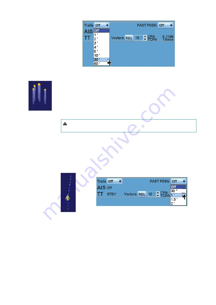
The selection indicates the time for the trails to fade out.

The picture on the left shows four targets moving in North direction, the lighter blue repre-

sent the trails. The lower intensity of the color, the longer time since the target was in that 
position. The trails are always processed, even if the operator decides not to display them. The 
system will not cancel any trail processing even when the operator changes the range scale, 
the True/Relative Motion display, or if a presentation reset is done. Once the operator chooses 
to display the trails, True or Relative, the calculated trails will immediately appear on the 
screen. Trails processing is interrupted and cancelled only if the operator changes the range 
scale repeatedly quicker than the time it takes the antenna to make a complete rotation, or if 
the Orientation Mode is changed.

 Caution:

 Trails build-up starts when exiting from the standby condition. Trails or past 

position length will be reached only after the selected time duration. 

Past positions

The Past Positions button function (See also “System data area sections” on page 23 and 
page 26) is to visualise the last four positions of each target. Pressing the button, a list will 
be opened, as in the figure on the left. The dots behind the target represent its position in the 
past multiple of “t” time, where “t” is the time interval selected from the list shown in the figure 
below.


This function is used to determine whether the target is manoeuvring or keeping a steady 
course. The path is displayed with up to 4 dots, spaced with a time interval defined by the 
selection in the list. True (T) past positions are visualized when in True Motion, relative past 
positions are visualized when in Relative Motion. “(T)” and “(R)” are indicated on the left side of 
the Past Position button.


¼

Note: 

The past positions are not shown if the radar target symbols are Off.

Vector time

The Vector Time label allows setting the length of the vector drawn from the bow of each 
target. The vector lengths are computed multiplying the target speed by this time value; 
therefore, the length of the vector, represents the echo position according to the set minute’s 
value. The line of the vector is dashed.

Содержание ARGUS FMCW 3G

Страница 1: ...ENGLISH ARGUSRADAR SYSTEM User Manual navico commercial com...

Страница 2: ......

Страница 3: ...ict between any Translation of the Documentation the English language version of the Documentation will be the official version of the Documentation This manual represents the product as at the time o...

Страница 4: ...or death Warning An operating or maintenance procedure practice condition and statement which if not strictly observed could result in damage to or destruction of the system or reduced performance No...

Страница 5: ...ust be highlighted Whenever a precaution relating specifically to a part of this manual is needed the informa tion is given in the relevant part of the manual Warnings and Cautions precede applicable...

Страница 6: ...proach closer than 1 foot 12 cm from the unit unless front cover is in place Radio frequency radiation Harmful effects particularly to the eyes may be caused by exposure of any part of the human body...

Страница 7: ...entation wide screen 26 General operating procedures 26 GUI Widgets description 26 Buttons 27 Labels 27 Shortcuts 27 Spin buttons 28 Switch buttons 28 List boxes 28 Combo boxes 28 Check buttons 28 Pro...

Страница 8: ...Course Up 62 Relative motion RM 62 True motion TM 62 P reset TM reset 63 The row under PPI area 63 Range scale increase decrease 63 Range rings on off 63 PPI Centre Off centre 64 P reset TM reset 64...

Страница 9: ...t trails 100 Past positions 100 Vector time 101 True Relative vector 101 Tracking menu 102 Anchor watch 102 Training target 102 Cancel ALL TGT 103 Minimum safety menu 103 Auto Acquisition zone 103 Gua...

Страница 10: ...s 135 Operating modes fallback 136 Maintenance 137 ARGUS FMCW radar 137 General 138 Additional benefits of FMCW radar 139 FMCW radar scanner specifications 140 Overall dimension of FMCW radar 140 FMCW...

Страница 11: ...one monitor to the next The graphic layouts and widgets in this manual are examples only and may therefore not appear exactly the same on the screen in your system In order to reduce the number of cir...

Страница 12: ...Depth DR Dead Reckoning DSC Digital Selective Calling DW Deep Water EBL Electronic Bearing Line Abbre viations Terminology ECDIS Electronic Chart Display And Information System ECS Electronic Chart Sy...

Страница 13: ...RM Relative Motion RM R Relative Motion Relative Trails RM T Relative Motion True Trails RNC Raster Navigational Chart Abbre viations Terminology RNG Range ROT Rate Of Turn RR Range Rings RTE Route R...

Страница 14: ...ECDIS interface ARGUS P 340 WS 320 mm 100 300 110 ARGUS P 340 320 mm 100 300 110 ARGUS P 250 250 mm 100 300 110 ARGUS P 25O WS 250 mm 100 300 110 ARGUS P 180 WS 180 mm 20 120 20 To better understand...

Страница 15: ...ing main parts protected in a dedicated cabinet the Antares Assy the Alpha Board the optional Alpha Expansion Board the Power Supply mounted on the Alpha Board the Line Filter the Main Power Switch Fo...

Страница 16: ...cks the digital signal is processed by means of complex algorithms in order to recognise the presence of a target and if the target is present its shape and the target coordinates The target coordinat...

Страница 17: ...24 1 CAT2 CAT2H Monitor size 23 320 mm 1600 x 1200 1 CAT1 CAT1H Monitor size 26 WS 320 mm 1920 x 1200 1 CAT1 CAT1H Monitor size 27 WS 320 mm 1920 x 1080 1 CAT1 CAT1H Performance for categories of ship...

Страница 18: ...in ship name and distance Safe Checking All AIS targets in sleeping or activated state Auto acquisition Guard Zones Same zones described in Radar Target facilities Trial manoeuvres Trial course For A...

Страница 19: ...in Guard Zone Lost Target Sys tem Failure and external interface sensors EPFS and AIS Other features Anchor watch echo reference speed not for AIS enabled systems EPFS speed Built in electronic dual...

Страница 20: ...round speed sensor is required to be con nected to the Argus console Only electronic positioning systems EPFS approved in ac cordance whit the requirement of the IMO in resolution msc 112 73 shall be...

Страница 21: ...er switch of the core unit must be set to position 0 2 TX ON This pushbutton is used to switch the system between Standby and TX ON In Standby the display does not request the TXRX to transmit but it...

Страница 22: ...n referred to Heading Line NORTH UP Momentary pushbutton used to select North Up presentation referred to Gyro North When the PPI is in True Motion mode the presentation is automatically selected For...

Страница 23: ...This feature is important in case of switching on during the night to avoid a strong flash into the eyes of the operator For daylight operation click on the centre mouse key or press the BRILL button...

Страница 24: ...d set the scanner in transmit mode When transmitting the fol lowing window will be displayed on the screen MonitorDisplay Generalview The window displayed can be divided into the following two main ar...

Страница 25: ...s Radar Operator Manual 1 Own ship 2 Help line 3 Operating mode 4 Cursor 5 Tracking 6 Main menu control 7 Displaying information 8 Video processing 9 Alerts System status Failure 10 Presentation modes...

Страница 26: ...Main menu control By pressing the main menu a dropdown menu with submenus will be displayed Refer to Main menu on page 43 for the explanation of these submenus 7 Displaying information In this sectio...

Страница 27: ...o view the different sensors Monitordisplay Widescreen The window displayed can be divided into the following two main areas PPI area in which the video radar is displayed In this area upon command of...

Страница 28: ...rmation is available in the ARGUS radar display A general description of the GUI which describes each section of the System data area is provided in Own ship section on page 35 GUI Widgets description...

Страница 29: ...function keys on the keyboard on page 29 The Normal labels are just indications they don t have any frame or focusing function The data that they contain can be in two different colors depending on th...

Страница 30: ...st is open clicking outside the List box or on the button the list will automatically close with no effect Combo boxes The Combo boxes look very similar to the List boxes They are lists of items displ...

Страница 31: ...eft SK takes the target acquiring function and once clicked the echo under the trackball pointer will be acquired Other example when the trackball pointer is placed on an editable label the 3 labels o...

Страница 32: ...s editing Place a Map text on PPI only in Maps editing Place a Map symbol on PPI only in Maps editing Ins Symbol Cancel Txt Angle Adj The displayed Map will be hooked to be moved in the next step Quit...

Страница 33: ...t speed as speed source Manual speed as speed source LOG A Drift Manual Set LOG speed as speed source Set auto drift speed as speed source Manual speed as speed source LOG EPFS Manual Set LOG speed as...

Страница 34: ...not possible to perform any action and the focusing does not work When it is enabled again the focusing will work and it will be possible to run the relevant action Clicking in the ARGUS interface In...

Страница 35: ...function such as the Gyro preset and need to fill in data a nu meric or an alphanumeric keyboard will be displayed right below the cursor section See Sys tem data area sections on page 23 pos 4 The o...

Страница 36: ...label will be displayed amplifying the information related to the function performed and labelled on each button Small menu like icon If the button is labelled with a menu like icon its function is t...

Страница 37: ...t the proper angle between the ship s heading and North in case of incremental gyro such as Stepper or Synchro Operating with an incremental gyro the value provided by the gyro compass is only the inc...

Страница 38: ...s the third phase S3 4 The last one is D36 and it is to indicate the reference Move the Gyro or somehow simulate a turn and the three LEDs S1 S2 and S3 will start to change their state it will be easy...

Страница 39: ...al axis STW WT W Serial dual axis WT choice STW WT W BT choice SOG BT BT Manual speed Manual drift ON STW MAN n a M Manual drift OFF SPD MAN n a M Echo reference speed SOG REF BT R EPFS speed SOG EPFS...

Страница 40: ...n of the Help line which will say Decrease Enter Value and Increase then press the left or right SK to decrease or increase the actual value or press the centre SK to directly enter a new value using...

Страница 41: ...ically be switched to LOG If the LOG is working on water track the speed mode will become sea stabilised EPFS speed Selecting the EPFS speed own ship s speed is taken by the speed information coming f...

Страница 42: ...e GPS Invalid data is displayed in red low integrity data in black on a yellow background When the EPFS is not available or in timeout the geographic position value is replaced with a red UTC or local...

Страница 43: ...on depends also of the datum DTM used The DTM sentence is processed and evaluated Latitude and longitude will not be accepted and presented when the reference datum is different from WGS 84 no datum h...

Страница 44: ...cted CCRP Position Consistent Common Reference Point By pressing this button it is possible to change the CCRP position between the conning position and the radar antenna Every measurement made with c...

Страница 45: ...ocessing page 75 TXRX and Interswitch Menu page 77 Brilliance Settings page 50 Orientation Motion Sharing page 51 and Mode Selection page 61 Day Color page 50 Cursors page 41 Antares PCB Info page 50...

Страница 46: ...preferences Bearing scale accuracy Around the PPI window the degrees are indicated on the Bearing scale The values are nor mally set for every 30 degrees The bi stable button on the left top corner of...

Страница 47: ...Menu Dark Gray Choosing one of the above options from the list the colors of the graphic user interface will change consequently as shown in the following pictures Note The palette change has effect o...

Страница 48: ...eo level Echo Sharpening The echo sharpening Video radar histogram is deactivated as default The function is able to normalize relative color gradients 240 in the current radar presentation on scales...

Страница 49: ...ons In order to avoid repetition of procedures specific to the desired operating mode it is possible to save and recall specific operating functions There are three buttons which allow recalling these...

Страница 50: ...ecuted and the F1 button changes its background to yellow which means that it is the one currently activated Now if the FK1 is pressed again the system deactivates the functions from FK1 and restores...

Страница 51: ...th proportional outline This condition is usually reached only in the lowest range scale To permit a ship outline indication also in other range scales the limit can be set alternatively to 2 mm Layou...

Страница 52: ...knob on the keyboard The default option is the night background in order not to disturb the operator if the system is powered up at night time Meaning that every new system will start up with the nig...

Страница 53: ...configuration the recipient has to accept it by consenting to the new setting However in case of the Day Night Control parameter when this is set on any machine it is automatically changed on all othe...

Страница 54: ...console The point to point connection address of the ECDIS console is defined under the Radar Configuration menu See the Installation Manual for a description of the ECDIS con nection setup Up to two...

Страница 55: ...ting the obstacles present close to the route or coastlines By increasing the scale we can see that the Waypoint also shows a radius of curvature where the ship changes direction These maps are enrich...

Страница 56: ...areas on the system data area section entering the tasks to be set into the dedicated areas The sensitive areas for which we can configure our Tasks have been highlighted in the figure below Settable...

Страница 57: ...desired name for this type of configuration e g DEFAULT In this mode it is possible to save up to 16 configurations To re use this type of configuration just search for the previously saved name and...

Страница 58: ...indow shows the speed through water STW and the speed over ground SOG Docking The window shows the speed over ground SOG this is used during docking manoeuvres Steering gear The window shows the rud d...

Страница 59: ...the first window Conning Tasks Editing Mode Picture in picture Title Adjustments CCTV TaskCCTV Rescaling and moving the CCTV window is only possible using the spin buttons which then make it possible...

Страница 60: ...n To present the AIS symbols on the 2nd PPI select the window AIS symbol If you wish to see the tracked target symbol select TT Symbols For more information about the symbols used see Horizontal line...

Страница 61: ...of eight times Once the function has been enabled it is possible to interact through one of three options Relative This means the possibility to follow your course throughout the route viewing the su...

Страница 62: ...Ls Off or last settings Fixed range rings Off Gain Rain and Sea Automatic Graphical AIS reported target display On Off centering Look ahead Operational alarms except collision warnings Off Parallel in...

Страница 63: ...ails stands for Relative Trails and T Trails for True Trails The Reset Course button is enabled only if a Course Up is selected Its function is to reset the presentation to the actual Course Up for ex...

Страница 64: ...o own ship s course and speed while the radar image is displayed according to its true movement land is steady and other ships are moving If own ship position exceeds 50 off centre on the PPI its posi...

Страница 65: ...scale NM Pulse length s PRF Hz 0 125 0 07 3000 0 25 0 07 3000 0 50 0 07 3000 0 75 0 07 3000 1 5 0 07 3000 3 0 07 3000 6 0 25 1500 12 0 25 1500 24 0 80 750 48 0 80 750 96 0 80 750 The PRF is controlled...

Страница 66: ...ange rings maps etc will be hidden The button is mono stable so releasing it the PPI graphic is visual ized again therefore the button must be kept pressed to keep the PPI graphic invisible Tune The f...

Страница 67: ...to a thin double horizontal arrow Gain The gain progress bar shows the gain level adjusted by the operator by means of the SKs used placing the trackball cursor inside it its function is to control t...

Страница 68: ...arget echoes and rain clutter is not to look at signal amplitude but at their rate of change in range That is exactly what the manual rain control is doing it works as an FTC fast time constant filter...

Страница 69: ...that a clear scan is almost impossible without cancelling interesting echoes The sea clutter can be suppressed with the manual sea control This one reduces the signal received following an attenuatio...

Страница 70: ...igure will appear giving the possibility to select a different sea state or the Auto Adaptive Sea Control Selecting one of the possible items the indication in the progress bar will change consequentl...

Страница 71: ...ates that all presets are disabled Interference rejection The function of the Interference Rejection is to eliminate the mutual radar interference and second trace echoes Pressing the IR button placed...

Страница 72: ...distinguish real target echoes from sea clutter Correlation is performed by storing and averaging echo signals over successive picture frames If an echo is solid and stable it is presented in its norm...

Страница 73: ...etween two subsequent transmitted pulses is subject to small variations the second trace echo ap pears undefined and hazy These echoes will be displayed at their correct bearing but at a wrong range g...

Страница 74: ...Scale The reason why when looking for a SART it is preferable to use from 6 to 24 NM range scale is because the length of the SART response of 12 dots may be extended to 9 5 NM beyond the position of...

Страница 75: ...range scale to under 6 NM it is recommended to return to the Standard Video Proc As the SART is very near side lobes from the radar antenna may show the SART responses as a series concentric arcs or r...

Страница 76: ...nge with the country it is placed in Generally they are used for identify aids to navigation both seaborne buoys and land based lighthouses identify landfall or positions on inconspicuous coastlines i...

Страница 77: ...reset with center mouse button The scope of the function is to provide shortcuts to adjust the radar at the best for the 6 con ditions giving the possibility to perform any desired change to better ad...

Страница 78: ...scales 3 NM The system is always working on short pulse Echoes are enhanced to increase visibility Sea clutter residuals are filtered by scan to scan correlation Medium range Should be selected when...

Страница 79: ...the radar system to be Master or force the operating display in Slave mode In Slave the TXRX is not controlled by the operating display If the transceiver is controlled by another display or if it is...

Страница 80: ...func tion and the button are disabled Power normal boost Pressing the Power Normal button TXRX interswitch menu standard on page 77 the Power Boost function will be displayed This function permits op...

Страница 81: ...the displays connected to new transceivers mosfet can show the infor mation indicated in the above display Some systems do not show all this information it is just an example of the most detailed data...

Страница 82: ...X Data please see more details in TXRX interswitch menu standard on page 77 Tracking and video processing operation in combination and 2nd PPI mode When using the additional PPI the source and targets...

Страница 83: ...mode should be used for better detection on distant echos after previously suppressing clutter caused by sea waves or rain A and B combination Selecting the A and B detection mode in case of strong se...

Страница 84: ...tation To get around this problem it is possible to set the received angle first selecting the transmit ters TXRX 1 and TXRX2 changing its value with the spin buttons see Blind Sector below or using t...

Страница 85: ...re not synchronized are being com bined the delay between the updates of the two images can be as much as one scan of the antenna the fastest one If the ship manoeuvers at a speed above 40 min the sam...

Страница 86: ...PS this measurement mode will also indicate the geographic position of the echo right under the range and bearing See System data area sections on page 23 Curser and Markers section 2nd and 3rd row Me...

Страница 87: ...s a more accurate measure ment of the range to an echo The two VRMs will be visualised on the PPI as dashed rings so that the operator will be able to dis criminate them from the fixed range rings The...

Страница 88: ...dd hh mm To display ETA and TTG the cursor must be placed inside the PPI at a bearing of 45 relative to own ship course Notes ETA can be displayed only if an external time source is connected i e GPS...

Страница 89: ...selecting the ERBL 1 and VRM 1 to display them independently Parallel indexes To enable their visualisation the buttons on the first column on the left related to the paral lel indexes where the On Of...

Страница 90: ...has its own list where it is possible to choose an individual alignment option Parallel to HL STBD Parallel to HL Port Parallel to EBL STBD Parallel to EBL Port Following PI x from 1 to 4 with exclus...

Страница 91: ...lso the status of the Parallel Index function When not enabled a red cross is overlayed the PI icon When the Truncate mode checkbox is selected the parallel indexes can also be truncated The effect is...

Страница 92: ...he manual sea rain controls or select the automatic sea rain controls Tracked targets entering these areas could not work properly Generally the effects of such errors appear as continuous big changes...

Страница 93: ...t way The confirmation delay is about five scans and after that some additional time is needed to reach the same data precision as from before the manouvre Tracking operation in 2nd PPI zone and under...

Страница 94: ...portionally to the ship s speed And if the speed is higher than 14 Kn the refresh rate is about 2 seconds As mentioned above the AIS can in theory control up to 5000 ships It is important to underline...

Страница 95: ...ff button from the tracking menu see page 101 The AIS will cease to operate when the corresponding On Off button or the label in the system data tracking section is set to AIS Off Own ship positioning...

Страница 96: ...symbol AIS target Sleeping aligned with received heading information or with COG information if heading is not available AIS target activated True scaled outlines AIS target with heading line and SOG...

Страница 97: ...d color The symbol flashes until the target alarm is acknowledged by the op erator It remains red until the system no longer defines it as a danger ous target Radar target in acquisition state indicat...

Страница 98: ...rtual AIS AtoN East cardinal mark Virtual AIS AtoN Emergency wrek mark Virtual AIS AtoN Isolated danger Virtual AIS AtoN North cardinal mark Virtual AIS AtoN Port hand mark Virtual AIS AtoN Safe water...

Страница 99: ...he target message data the speed datum is not received the CPA TCPA computing will be impossible and the AIS target will assume a symbol of a big dotted triangle If a radar target and an AIS target ar...

Страница 100: ...mum AIS limit the warning message ACTIVE AIS CAPACITY ABOUT TO BE EXCEEDED is displayed When the limit of maximum active AIS is reached a new activation replaces the farthest AIS and the message WARN...

Страница 101: ...ading is necessary 3 Information such as the beam and length of the ship is needed 4 AIS conning position coordinates are required 5 It is not possible to draw an outline for targets such as ATON or S...

Страница 102: ...r the selected time duration Past positions The Past Positions button function See also System data area sections on page 23 and page 26 is to visualise the last four positions of each target Pressing...

Страница 103: ...tive vector The True Relative Vector button function See Relative motion RM on page 62 and True motion TM on page 62 is to toggle the visualization of the vectors on the PPI between True and Relative...

Страница 104: ...e Training button to On and a simulated target will be shown as a small x The training target speed can be changed by means of the SKs placing the cur sor on the relative spin box next to the Training...

Страница 105: ...hould be adjusted in order to exclude the sea clutter Back range radius of the back range Back sector angle in degrees of the back blind sector This value should be adjusted to ex clude own ship wake...

Страница 106: ...ard Once they are accepted the active ones are drawn with a standard line The others are cancelled from the screen If a zone during editing overlaps an active zone it will be flashing And if the opera...

Страница 107: ...e accurate estimations are made when the speed source is sea stabilised The Trial Manoeuvre can be performed in Manual or Automatic mode In Manual mode the final course must be manually entered by the...

Страница 108: ...n searching for the safe course Note that if no target is in risk of collision and the operator order an Auto matic Trial Manoeuvre the system will confirm the actual course and nothing will change Th...

Страница 109: ...s section System data area sections on page 23 If the Automatic Trial Manoeuvre gets an unsuccessful result the operator can Modify the minimum safety limits if they are for instance too high the mano...

Страница 110: ...derstand if a steering to 0 is safe so he performs the manual trial manoeuvre to foresee the situation at the end of the steering he intends to do AutomaticTrialManoeuvrescenario During and at the end...

Страница 111: ...on In practice when an echo with its AIS symbol on top is being acquired for tracking the sys tem can detect that the two symbols represent the same target The symbol displayed after the association i...

Страница 112: ...the above conditions has changed Note If more than one radar tracked target is in the above mentioned thresholds only the closer one will be fused The data from the AIS button is used to change the so...

Страница 113: ...the AIS targets exceeding that limit It is possible to set the priority by RANGE Only the ones closest to own ship will be accepted DANGER Only the most dangerous will be accepted Danger is evaluated...

Страница 114: ...r Auto Activation Disabled This checkbox can disable the automatic activation for AIS that becomes dangerous Symbol Pressing the Symbols labelled button the Graphic Symbols Menu will be displayed This...

Страница 115: ...uate the actual traffic situation Initially after acquisi tion of a radar tracked target the system will not have enough data to provide a reliable vec tor and only the initial state symbol will be di...

Страница 116: ...st or Danger Ship Name Available only with AIS tracks For radar target the field is indicated with MMSI Maritime Mobile Service Identity Available only with AIS targets For radar target the field is i...

Страница 117: ...Therefore by means of the right SK the presentation can be switched to 4 targets mode changing the target data window as shown below Fourtargets Switching from 2 to 4 targets presentation the 3rd and...

Страница 118: ...mation displayed are 1 Type of ship 2 Nav status 3 Destination 4 ETA 5 ROT 6 BCR 7 BCT With the 2 targets mode pressing the left SK in the field of a radar tracked target the extend ed data window wil...

Страница 119: ...ally all the data is available immediately Only the static data such as Ship Name Ship Type Call Sign Destination ETA Status could be unavailable if the target is being selected before the detection o...

Страница 120: ...e Vector True Speed and Course Relative Vector Relative Speed and Course Furthermore the background of the labels will change to red color if their values are incoher ent with the motion mode 1 Relati...

Страница 121: ...absolute position if EPFS is available Note In case the EPFS or the Gyro is in failure or invalid it is not possible to display Geograph ic Map And in case of Log or Gyro failure also the Dead Reckoni...

Страница 122: ...and color of the next lines he is going to draw the color of the next text he is going to write and the type and color of the next symbol he is going to place Clicking inside each of them the followin...

Страница 123: ...erted the Select Sym button will be enabled How to do modifications Once the Select Line Select Text and Select Sym buttons are sensitive the operator has the possibility to select an already drawn ob...

Страница 124: ...p Normally the origin of the map is own ship position It can be moved from that position if the map has been shifted The Help line will show Unused Undo Adj and Apply Rot Note that to anchor the map t...

Страница 125: ...stead of Start New Line and Update Changes instead of Store New Map The three labels in the lower part will indicate the number of lines texts and symbols com posing the map If one of them is zero the...

Страница 126: ...hted line press the centre SK and the following window will appear The buttons of the left column allow changing the line style and the ones of the right column allow changing the line color The Accep...

Страница 127: ...e also Geographic map manual settings menu If a recalled map is of a geographic type or if an Under Construction is being build as geo graphic type a new button labelled as Geo Maps Manual Settings wi...

Страница 128: ...of a line it will be highlighted with a green circle as shown in the picture For the texts and the symbols highlighting will appear as a rectangular frame around texts and symbols This highlighting i...

Страница 129: ...as when changing the latitude figure so pressing the right SK the object following the one already selected will now be selected and so on For example pressing the right SK with the trackball pointer...

Страница 130: ...stick inserted into the USB port on the keyboard The System Maps list includes all maps stored inside the ARGUS radar USB maps lists all the maps saved on the USB memory stick Use the trackball pointe...

Страница 131: ...als repeated every 7 sec onds and the alarm icon is flashing until the alarm is acknowledged Warnings This is alerts of lower priority announcing conditions that could result in un wanted system respo...

Страница 132: ...lashing symbol and descriptive text No audible signal Rectified not acknowledged Flashing symbol and descriptive text No audible signal Caution Active Steady symbol and descriptive text No audible sig...

Страница 133: ...e failure is unrecoverable this small symbol will stop the system failure light on the control panel will flash and the system fail relay output will be activated Alphabetic alarm listing The followin...

Страница 134: ...Invalid W Position Source in use Failure W Position Unavailable W Radar Antenna Failure W Radar TXRX Failure W Radar Video Failure W Reference Target Lost W Source of Speed in use Failure W Speed Lon...

Страница 135: ...speed source WRONG Cannot read map Not possible to read map WRONG Cannot write map Map cannot be written WRONG Cursor outside PPI The cursor is not inside the operative area WRONG Delay Time Too Long...

Страница 136: ...nnot be done for TXRX3 and 4 WRONG Offcenter 50 Not allowed an off centre superior than 50 of PPI WRONG Out of Memory No more memory available WRONG Out Of TT Max Range Impossible to track over 24 NM...

Страница 137: ...lure occurs Failure Possible alert Fallback arrangement Function inhibited AIS input failure AIS FAIL AIS Course and speed over ground failure Speed LOG FAIL SOG FAIL EPFS speed FAIL Automatic switch...

Страница 138: ...ssible anomaly such as the integrity of the equipment the presence of rust missing paint and loose screws It is required by the operator to clean the equipment and remove dust ash and grease if necess...

Страница 139: ...bursts of high power microwave energy periodically and the radar detector listens to the echoes coming back from each pulse As the radar rotates these echoes are built into a 360 degree image Firstly...

Страница 140: ...W radar can see within a few meters of the boat compared to pulse radars which can not see closer than 30 meters higher resolution clearly separates individual vessels and objects up to five times bet...

Страница 141: ...utside dimensions Height 280 mm 11 02 x Diameter 488 mm 19 28 Weight no cable 7 4 kg 16 31 lbs Radar and antenna parameters Radar Ranges 50 m 200 ft to 24 nm with 17 range settings nm sm km SINGLE RAN...

Страница 142: ...equire that the FMCW is switched on and is in the same IP area as ARGUS Once the function is activated the FMCW pushbutton will be avail able in the system also after the system has been turned off Fi...

Страница 143: ...press the red pushbutton for the system to carry out the modifications manu ally later In both cases it is necessary to know exactly what is happening particularly because the automatic configuration...

Страница 144: ...nabling the transceiver is necessary for its utilization Position of the FMCW transceirer B Spin buttons B permits entering the coordinates of the transceiver s position on the ship These parameters a...

Страница 145: ...eters cannot be modified by the user because they belong to the FMCW transceiver radar system Transceiver position H In box H a precise position can be assigned to an FMCW transceiver that will be uti...

Страница 146: ...ard 24 rpm Medium 36 rpm High 48 rpm A B InterswitchmenuwithFMCWtransceivers Description of commands relative to the window of the FMCW radar trans ceivers Attention More than one console can utilize...

Страница 147: ...color of the image transmitted from the radar The different colors for the Menu are The different colors for the Video are Light Blue Yellow Dark Blue Green Light Green White Dark Green Multi Light G...

Страница 148: ...Transmission An area inside the window that gives us immediate information about the type of transmission being used and therefore viewed in our specific case TXRX 5 FMCW Limits The ARGUS FMCW system...

Страница 149: ......

Страница 150: ...988 10185 004...

Отзывы: