


CN-Series Hardware Installation and Maintenance Guide
CN-Series Hardware Components
Callout
Component
Description
1
Power button
Controls power to the CN-Series system and indicates whether there is power to the
CN-Series system. If the indicator is green, the CN-Series system is receiving power.
2
Diagnostic
indicators
Show CN-Series system hardware error conditions.
3
System
identification
button
Finds a CN-Series system within a rack.
Push the system identification button on the front panel (or the back panel). The
system identification buttons on the front panel and the back panel flash blue until
you push one of the buttons again.
4
Retention latches Lock the CN-Series system enclosure in the rack, push to slide the enclosure out.
5
USB connector
USB 2.0-compliant connector. Enables you to connect a USB device such as a
keyboard as part of a KVM for local administration.
6
Video Input
Enables you to connect a monitor as part of a KVM, for local administration.
7
Storage
24 drives, size 2.5", with power (right) and activity (left) LED indicators.
Disks are numbered from 0 to 23, left to right. Disks 0 to 5 are SSDs. Disks 6 to 23
are HDDs. If you pull the CN-Series system enclosure from the rack, the disk
numbering scheme appears on a label attached to the top of the enclosure.
8
Service tab
Provides identification information that might be required during a technical support
session.
Related Topics
Technical Support and Customer Service
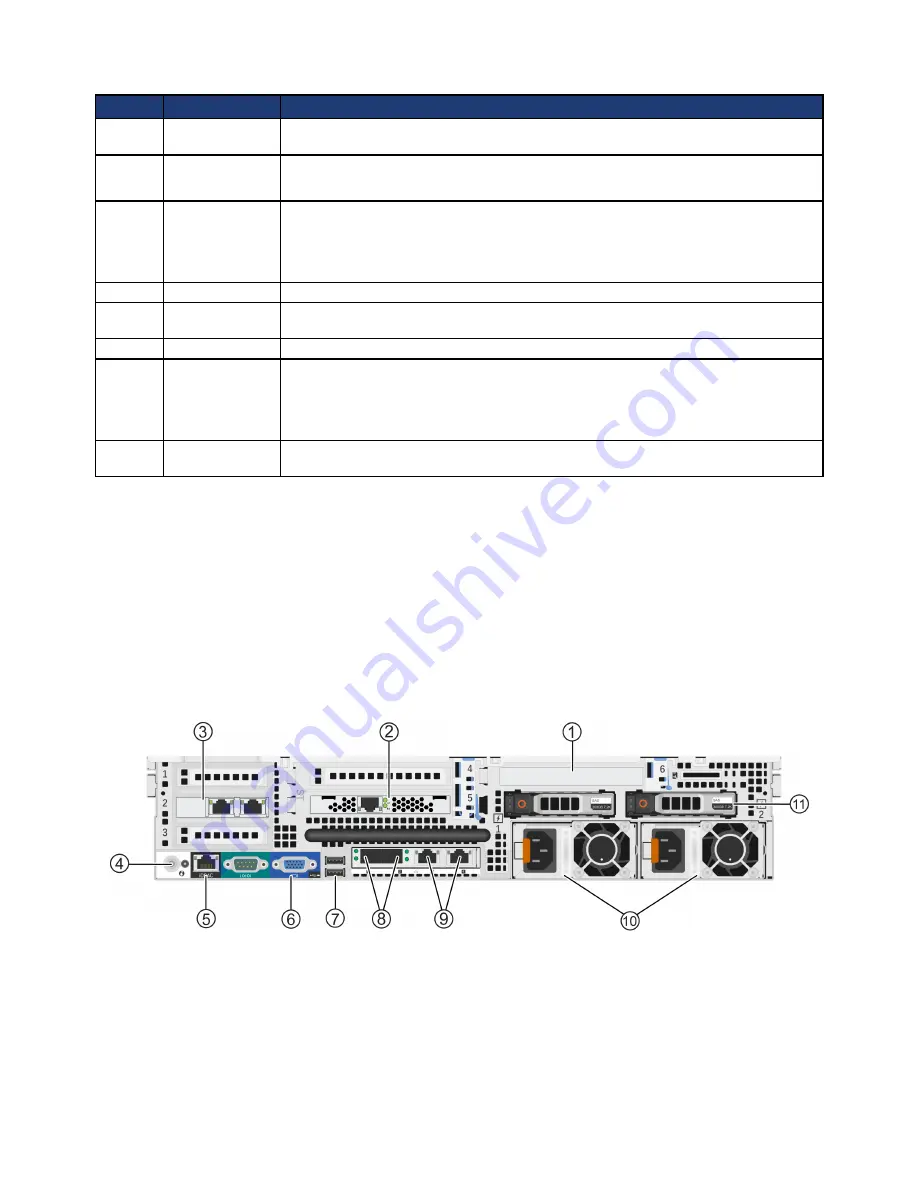
Back Panel Description
The following image shows the back panel of all 2U CN-Series systems.
The following table describes the components of the back panel.
10