background image

ATTACHMENT

OPERATOR’S
MANUAL

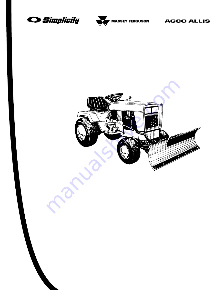
Snow Plow/Dozer Blade

Mfg. No.

Description

1693754

42” Remote Angling Snow Plow/Dozer Blade

Hitch

Mfg. No.

Description

1693757

Hitch (for Sovereign / 900 / 2800 Series)

1721303-01

Rev 1/2001

TP 100-2374-01-AT-SMA

Snow/Dozer

Blade & Hitch

Содержание 1693754

Страница 1: ...AL Snow Plow Dozer Blade Mfg No Description 1693754 42 Remote Angling Snow Plow Dozer Blade Hitch Mfg No Description 1693757 Hitch for Sovereign 900 2800 Series 1721303 01 Rev 1 2001 TP 100 2374 01 AT SMA Snow Dozer Blade Hitch ...

Страница 2: ...ring Inc All Rights Reserved Printed in USA TP 100 2374 01 AT SMA Recommended Accessories 1 Safety Rules Information General Warnings 2 Operating on Slopes 2 Preparation 2 Operating Safety 2 Features Controls 3 Blade Angle Control 3 Attachment Lift 3 General Operating Instructions Checks Before Starting 4 Engine Ground Speed Selection 4 Transporting 4 Starting Stopping 4 Changing Angle of the Blad...

Страница 3: ... must be followed GENERAL WARNINGS Know the tractor controls and how to stop quickly READ THE TRACTOR OPERATOR S MANUAL Read this manual and the tractor Operator s Manual carefully Be thoroughly familiar with the controls and the proper use of the equipment Never allow children to operate the machine Do not allow adults to operate it without proper instruction Do not carry passengers Use only atta...

Страница 4: ...tion Move the lever slowly past center to lock in the centered position NOTE It is easier to change the angle of the blade with the attachment raised B Attachment Lift NOTE Models with hydraulic or electric lift should refer to the tractor operator s manual for lift control informa tion The attachment lift lever raises and lowers the dozer blade See the tractor operator s manual for control inform...

Страница 5: ...parking brake remove the key and wait for all moving parts to stop General Operating Instructions WARNING Perform the Safety System Interlock test found in your tractor Operator s Manual If tractor does not pass the test do not operate the tractor See your authorized dealer Under no circumstances should you attempt to defeat the safety system Use caution when plowing a snow covered area Snow can c...

Страница 6: ...ack down the dirt or gravel by driving the tractor over the leveled area Use any slight grade to your advantage doze down hill and set the blade angle so that the plowed mater ial is moving downhill as it leaves the blade Snow Plowing Tips Determine the best snow removal pattern before beginning Plan the pattern so that you avoid pushing snow onto cleared areas When land contour permits it is best...

Страница 7: ...s that have partial rotational or sliding movement should be lubricat ed periodically with SAE 30 weight oil Avoid applying excessive amounts of oil since this may cause a build up of dirt around the lubricated area making subsequent lubrication more difficult to accomplish WARNING To avoid serious injury perform maintenance on the tractor or dozer blade only when the engine is stopped parking bra...

Страница 8: ...skid shoes A up or down to desired height Tighten the bolts securely Figure 3 A Skid Shoes B Bolts Spring Tension See Figure 4 This snow plow dozer blade is spring loaded so that when the blade strikes a solid object the springs will allow the blade to release as shown rather than cause damage The blade will go back to its original position after object is cleared Figure 4 Dozer Blade Released Fig...

Страница 9: ...rod should slightly compress the spring creating downward pressure on the blade NOTE Always adjust the lift height before and after adjusting the downward pressure IMPORTANT NOTE DO NOT OVER COMPRESS THE SPRINGS In addition to providing downward pressure the springs are an elastic medium that absorbs shocks caused by bumps and cracks in ground surfaces Over compress ing the springs defeats this an...

Страница 10: ...APER BAR 14 6 CARRIAGE BOLT 3 8 16 x 1 15 10 LOCKWASHER 3 8 Ref Qty Description 16 6 NUT Hex 3 8 16 17 2 SKID SHOE 18 4 WASHER Plain 3 8 19 4 CAPSCREW 3 8 16 x 3 4 20 2 CAPSCREW 1 2 13 x 1 1 2 21 2 SPACER 1 2 ID x 3 4 OD x 5 16 LG 22 1 ROD Latch Stop 23 2 LOCKNUT 1 2 13 24 1 FRAME ASMY Dozer 25 2 EYEBOLT 26 2 SPRING Extension 27 1 CLIP Hair Pin 28 1 PLATE ASMY Latch 29 2 SPRING Torsion 4 6 4 1 3 4...

Страница 11: ... SPRING 7 1 ROD Lift Electric Hydraulic 8 5 CLIP Hairpin 9 2 CLEVIS PIN 10 1 PUSH BAR ASSY Front 11 1 PIVOT PIN Ref Qty Description 12 1 EYEBOLT 1 4 20 x 1 1 2 13 1 LOCKNUT Center 1 4 20 14 1 BRACKET Control Rod 15 1 WASHER 3 8 16 2 WASHER 5 16 17 2 LOCKNUT Flange Whizlock 5 16 18 18 2 CAPSCREW 5 16 18 x 1 1 2 19 1 BRACKET Control Rod 20 1 NUT Hex Full 5 16 21 1 LOCKWASHER 5 16 Figure 8 Push Bar H...

Страница 12: ...ust far enough so that it is flush with the end of the eye bolt 4 Hook the springs C into the pivot frame D Using a pliers stretch the springs to hook the opposite ends to the eyebolts A 5 Tighten the nut B on each eyebolt enough to expose about 3 4 19 mm of thread 6 Holding the first nut B with a wrench add a second nut E to each eyebolt and tighten securely against the first nut to act as a jam ...

Страница 13: ...rt prong of rod guide assembly H thru hole in upright of push bar Secure with spring clip I 6 Connect rear of lift rod J to tractor lift arm K using spring clip G Figure 12 Push Bar Installation A Tractor Hitch G Spring Clip B Clevis Pin H Rod Guide Assembly C Spring Clip I Spring Clip D Push Bar J Lift Rod E King Pin K Lift Arm F Spring Clip Assemble Lift Rod 1 Assemble lift rod per Figure 11 Lif...

Страница 14: ... D Secure using flange locknuts E 2 Install the eyebolt B in the support A and secure with a centerlock nut A B C D E Figure 14 Assemble Control Rods A 1 4 20 Centerlock Nut B Eyelet C Upper Control Rod D 5 16 18 x 1 1 4 Capscrew E 5 16 Washers Lockwashers Nuts F Lower Control Rod G Hair Pin Clip Washer A B C D F G E 3 Connect the lower angling rod F Figure 14 to the dozer release lever using a ha...

Страница 15: ...connect the angling control rod 3 Remove the angling control rod from the support arm A 4 Remove the pivot pin C connecting the blade and pushbar Remove the blade 5 Remove pin E securing hitch to the tractor 8 Reinstall all pins for storage Install in reverse order of removal Figure 15 Dozer Removal A Support Arm C Pivot Pin E Clevis Pins B Hair Pin Clip D Hair Pin Clip Washer D C B A B E C ...

Страница 16: ...ping screws thread forming screws sheet metal screws and socket head setscrews 2 Recommended seating torque values for locknuts a for prevailing torque locknuts use 65 of grade 5 torques b for flange whizlock nuts and screws use 135 of grade 5 torques 3 Unless otherwise noted on assembly drawings all torque values must meet this specification Hardware Identification Torque Specifications Common Ha...

Страница 17: ...16 NOTES ...

Страница 18: ...MANUFACTURING INC 500 N Spring Street PO Box 997 Port Washington WI 53074 0997 www simplicitymfg com Copyright 2000 Simplicity Manufacturing Inc All Rights Reserved Printed in USA ...

Отзывы: