


43
4.1
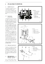
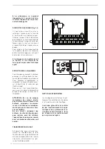
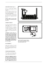
GAS VALVE
(fig..10)
“RMG P”
boilers.come.equipped.stan-
dard.with.a.HONEYWELL.VR.4400.gas.
valve..
When. the. boiler. is. ignited. the. first.
time,. it. is. always. recommended. to.
bleed.the.piping.by.using.the.pressure.
outlet.upstream.from.the.valve.
4.1.1 Gas pressure
on the main burner
The. pressure. is. adjusted. by. SIME. in.
the. production. line.. But. since. in. the.
place.of.installation.the.pressure.sup-
ply. values. can. change,. it. is. required.
to.verify.gas.pressure.and.flow.at.the.
first.ignition.
The. check. is. carried. out. by. reading.
twice.the.gas.meter,.with.a.six.minute.
interval,. and. with. the. boiler. conti-
nuously.operating.while.all.other.gas.
appliances
must.be.switched.off.
The. reported. consumption. must. be.
multiplied. by. ten. so. as. to. calculate.
the. hourly. consumption.. If. this. value.
does. not. match. the. one. listed. in. the.
technical.data.table.
(POINT 1.3)
,.turn.
the. screw. of. the. pressure. regulator.
(3). until. you. have. obtained. the. exact.
value.(turn.the
screw.below.the.plastic.cap).
We.recommend.that.you.perform.this.
operation. in. a. slow. and. gradual. way..
The. readings. on. the. meter. must. be.
made.at.least.thirty.seconds.after.you.
performed.the.pressure.adjustment.
This operation must always be per-
formed by authorized personnel.
4.1.2 Gas flow to the pilot burner
The. pilot. is. correctly. adjusted. if. the.
pilot. flame. covers. the. end. of. the.
thermocouple. for. a. 8-10. mm. length..
Adjustment.of.the.pilot.flame.is.made.
by.acting.on.the.screw.of.the.gas.valve.
(5).. To. increase. the. gas. flow,. turn.
the. screw. clockwise,. turn. it. counter-
clockwise.to.decrease.it.
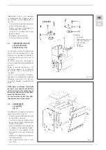
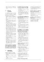
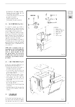
4.3
MAIN AND PILOT
NOZZLES REPLACEMENT
(fig. 11 - fig. 11/a)
To. replace. the. main. nozzles. proceed.
as.described.in.fig..11,.to.change.the.
pilot.nozzle.instead.proceed.as.descri-
bed.in.fig..11/a:
-..Loosen. the. screws. that. secure. the.
4 USE AND MAINTENANCE
Fig..11/a
KEY
. 1. Pilot.burner
. 2. Pilot.nozzle
. 3. Spark.plug
. 4. Interrupted.thermocouple
. 5. Gas.pipe
1
2
3
4
5
6
Fig..10
KEY
. 1. Ignition.button
. . (white.button)
. 2. Shutdown.button
. . (red.button)
. 3. Pressure.regulator
. 4. Coil.assembly
. 5. Pilot.flame.adjustment
. 6. Terminal.board
Fig..11
KEY
. 1. Boiler.body
. 2. Burner
. 3. Main.nozzle
. 4. Aluminium.washer
. 5. Burner.manifold
Содержание RMG 100 P
Страница 1: ...Fran ais English RMG 70 110 P Cod 6100019 11 2016...
Страница 2: ...1 2 3 4...
Страница 3: ...1 RMG P G20 G25 G30 G31 1 2...
Страница 5: ...2 1 RMG P 35 412 93 7131 72 7129 922 6 100 37 55 12 04 96 74 3 4 1 2 3000 2 2 1...
Страница 6: ...2 3 2 3 1...
Страница 7: ...2 4 1 2 5 500 20...
Страница 8: ...2 5 1 4 7129 92 35 2 6 230 50 3 60730...
Страница 9: ...2 6 1 IG TC EV TA TS TF T TA 3 4...
Страница 10: ...2 7 MAX MAX 80 60 MAX 50 30 MAX MAX MIN MIN 80 60 MIN 50 30 MAX MIN MAX GAS UK WRAS UK...
Страница 11: ...3 7...
Страница 12: ...3 2 8 4 4 1 10 V 4400 Di re 1 2 3 4 5 6...
Страница 13: ...4 1 1 SIME POINT 1 3 3...
Страница 14: ...4 1 2 8 10 5 1 2 3 4 5 11 11 1 2 3 4 5 6...
Страница 15: ...4 4 11 G30 G31 300 H2O 4 5 12 12 1 3 2 4 5 6...
Страница 16: ...7 4 6...
Страница 17: ...4 7...
Страница 18: ...6 7...
Страница 19: ......
Страница 20: ...14 15 20 60...
Страница 21: ...15 95...
Страница 22: ...16 OFF...
Страница 23: ......
Страница 48: ...48 FR EN NOTE...
Страница 49: ...49 NOTE...
Страница 50: ......
Страница 51: ......