47
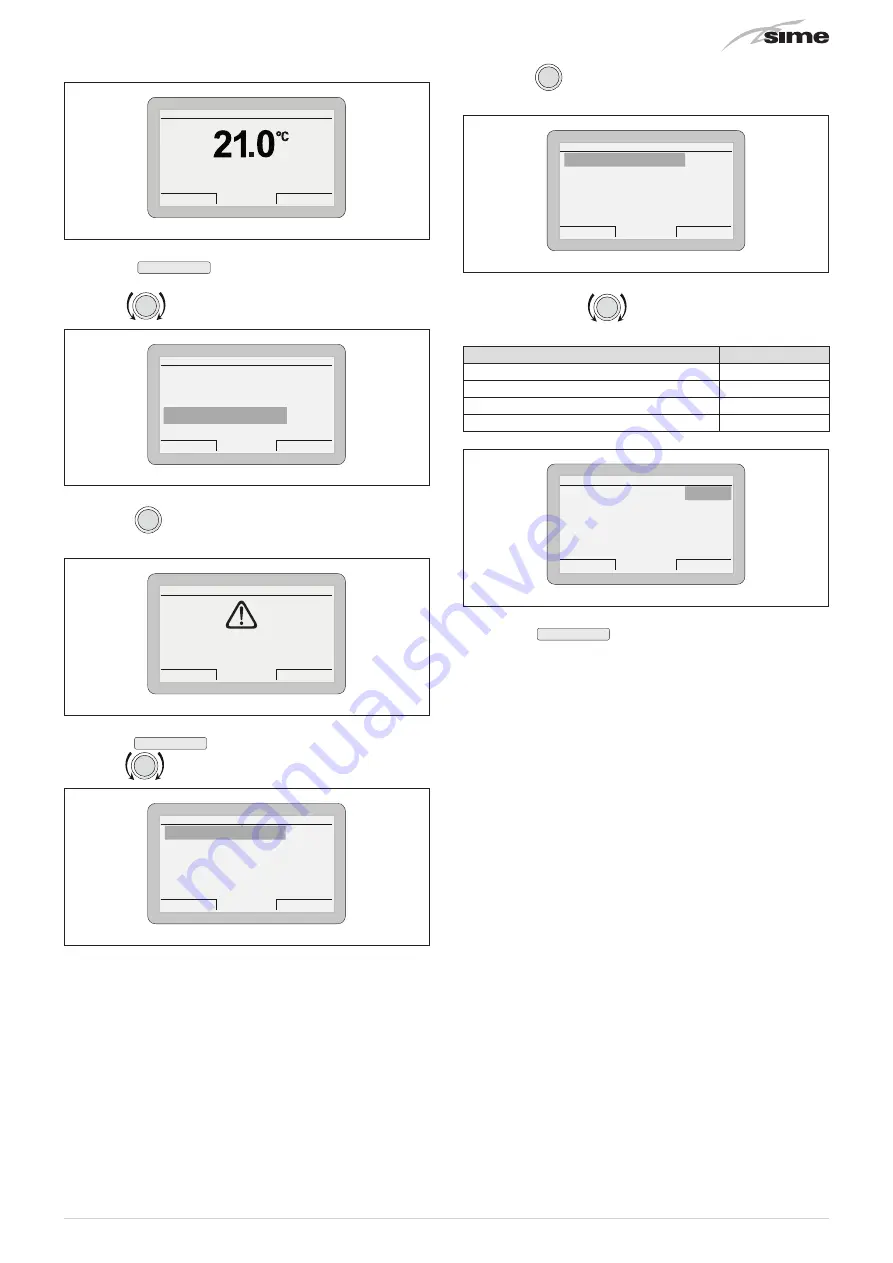
From the
“Main screen”
:
Thu 18 Set 2014
Zone
10:30
Menu
Mode
Off
Fig. 84
– press the
Menu
button to view the
“Menu”
selection
screen
– turn the
encoder to select the
“TECHNICAL”
menu
Esc
Back
GENERAL SETTINGS [...]
INFORMATION
[...]
TECHNICAL
[...]
MENU
Fig. 85
– press the
click
encoder to access the modifiable area. The
following screen is displayed:
Cancel
Confirm
CONFIRM REQUEST
Confirm operation?
Fig. 86
– press the
Confirm
button to access the submenus
– turn the
encoder to select the
“Zone heating”
submenu
TECHNICAL
Esc
Back
Zone
heating
[...]
Ht-boiler adjust. param.
[...]
Hot water
[...]
Boiler parameters
[...]
Advanced parameters Ht
[...]
Fig. 87
– press the
click
encoder to access the modifiable parame-
ters area
Zone heating
Esc
BACK
Req. from ext. TA
NO
Room probe run
YES
Room probe modul.
YES
Ext. probe modul.
YES
Weather comp.curve
4.0
Fig. 88
– press and turn the
encoder to change the settings as
specified below:
Req. from ext. TA
YES
Req. with room probe
NO
Mod. with room probe
NO
Mod. with ext. probe
YES
Zone heating
Esc
BACK
Req. from ext. TA
YES
Room probe run
NO
Room probe modul.
NO
Ext. probe modul.
YES
Fig. 89
– press the
Esc
button to complete the modification
and return to the
“Main screen”
.
The
main control panel (MCP)
then becomes a simple system op-
erator with the relevant operating logic, and requests for heat
for each zone are managed by the individual chrono-thermo-
stats or ambient thermostats.
5.14.3 EXAMPLE of use of the command/control de-
vice on some types of heating systems
KEY
M
System flow
R
System return
MCP
Main control panel (remote)
SE
External sensor
TA2
Room thermostat for boiler activation
TZ1÷TZ3 Room thermostat for the zone
VZ1-VZ3 Zone valves
RL1-RL3 Zone relays
P1-P3 Zone pump
SP
Hydraulic separator


