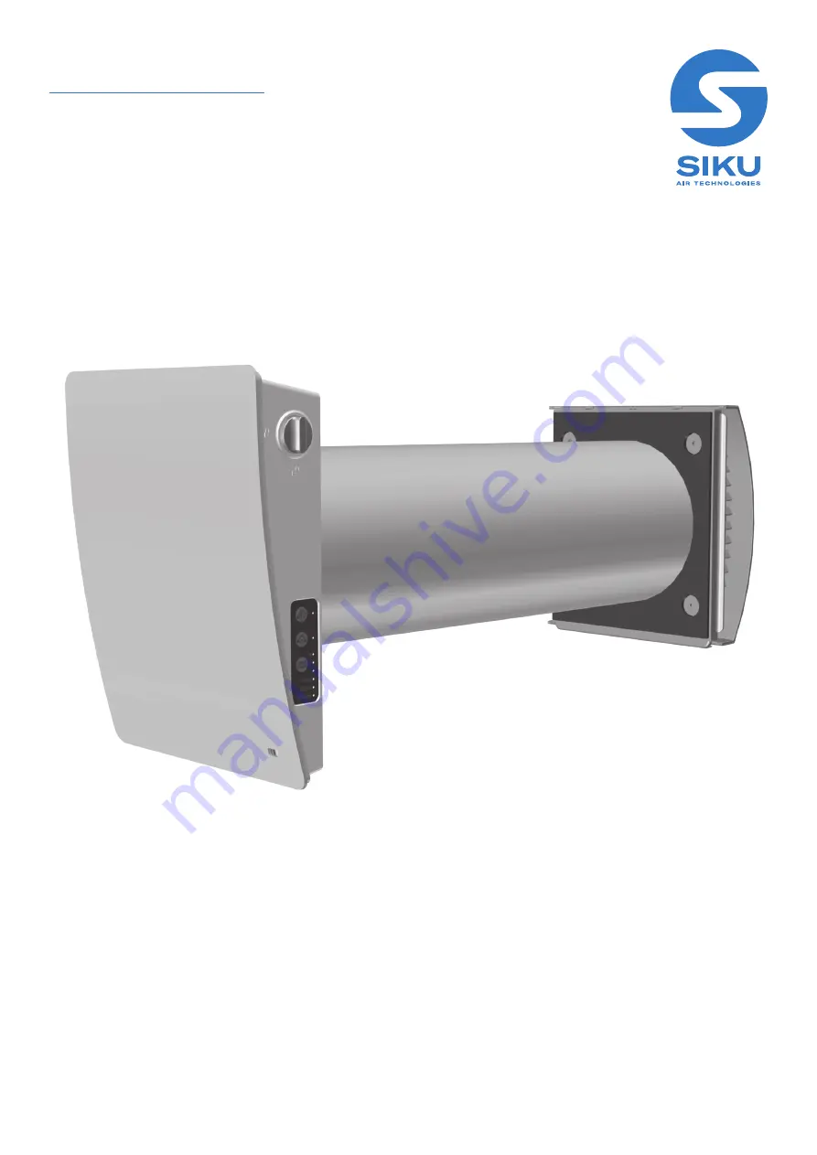
Single-room reversible energy recovery ventilator
USER‘S MANUAL
SIKU
SPHERE WiFi 100
SPHERE WiFi 160
siku.at
Страница 1: ...Single room reversible energy recovery ventilator USER S MANUAL SIKU SPHERE WiFi 100 SIKU SPHERE WiFi 160 siku at...
Страница 2: ...and standards must be observed when installing and operating the unit Disconnect the unit from power supply prior to any connection servicing maintenance and repair operations Only qualified electric...
Страница 3: ...e appliance The connection to the supply mains must be made through a mean for disconnection from the supply mains having a contact separation in all poles that provide full disconnection under overvo...
Страница 4: ...s SOUND INSULATION MAT 1 pcs CARTRIDGE 1 pcs OUTER HOOD 1 pcs REMOTE CONTROL 1 pcs CARDBOARD MOUNTING TEMPLATE 1 pcs MOUNTING SET 2 packs FOAM WEDGES 1 set INSTALLATION INSTRUCTION 1 pcs PACKING BOX 1...
Страница 5: ...I 100 SIKU SPHERE WIFI 160 VENTILATION LEVEL 1 2 3 1 2 3 SUPPLY VOLTAGE V HZ 100 240V 50 60 Hz POWER CONSUMPTION W 1 80 3 00 4 40 1 70 2 60 5 30 CURRENT CONSUMPTION A 0 03 0 04 0 05 0 03 0 03 0 06 DEL...
Страница 6: ...N SYSTEM Outer hood Protects the unit from ingress of water and foreign objects Each ventilator model has a matching ventilation hood model Outer hood with heating wire fitted Sound absorbing material...
Страница 7: ...n the network run in air supply mode and the other ones in air extraction mode depending on the position of the DIP switch No 3 see section Setting the ventilator operation mode using DIP switches Boo...
Страница 8: ...THE AIR DUCT OF THE INSTALLED VENTILATOR WITH DUST ACCUMULATING MATERIALS SUCH AS CURTAINS CLOTH SHUTTERS ETC AS IT PREVENTS AIR CIRCULATION IN THE ROOM WALL THICKNESS IS ABOVE THE MINIMUM WALL THICK...
Страница 9: ...o make assembly easier On the outer wall the ventilation pipe must protrude from the wall by the distance A which is required for the assembly of the external ventilation hood The distance A is 0 10 m...
Страница 10: ...oute the power cable as figured below and connect the ventilator to power mains in compliance with the external wiring diagram see section Connection to power mains Secure the power cable with the cla...
Страница 11: ...he sound absorbing layer in the air duct Roll the layer of the sound absorbing material to match the air duct diameter The protecting paper layer must be outside Insert the sound absorbing roll into t...
Страница 12: ...rd A3 in compliance with the wiring diagram and terminal designation Connect the unit to power mains through the external circuit breaker with a ma gnetic trip integrated into the fixed wiring system...
Страница 13: ...E OF THE VENTILATOR IN THE NETWORK 1 ON slave unit hereinafter referred to as Slave unit 1 OFF master unit hereinafter referred to as Master unit STANDBY MODE SETUP 2 Min the ventilator operates at Sp...
Страница 14: ...TONS ON THE INDOOR UNIT The speed selection sequence is follows I II III Standby All the units integrated in a single network operate according to the speed settings of the Master unit I permanent ind...
Страница 15: ...of Alarm blinking Battery charge is below the low level No connection between the Master unit and the router Alarm shutdown of the ventilator If several connected ventilation systems are running in a...
Страница 16: ...the DIP switch 3 Timer control buttons Party mode the timer activates operation of the unit at Speed III for a set time period 4 hours by default The timer setting may be changed during setup of the u...
Страница 17: ...teps below 1 Enter the app menu 2 Select Connection At home 3 If the mobile device is connected to the Wi Fi access point of the unit without a router select the Default connection 4 In case of connec...
Страница 18: ...Speed I timer without changing the ventilator operation mode 8 hours by default adjustable in the Settings Timers menu Weekly schedule Party mode Activation of the Speed III timer without changing th...
Страница 19: ...Choose the connection and press the Settings button 2 Enter and confirm the password 3 Press the Change Password button AIR FLOW SETTING To set the air flow corresponding to each of the three speed m...
Страница 20: ...eration via the mobile app go to Menu Settings Sensors Humidity sensor activation of the humidity sensor When the indoor humidity exceeds the set point the unit switches to Speed III When the humidity...
Страница 21: ...acturer is 90 days The need to replace the filters is sig nalled by the indicator in the upper section of the Control menu Reset the filter timer after replacing or cleaning the filters To reset the f...
Страница 22: ...nit responds to a signal from sensors as a humidity sensor an external digital sensor an external analogue sensor 0 10V and changes its operation mode respectively Slave The unit acts as a driven unit...
Страница 23: ...odern network devices WPA_WPA2_PSK password protected recommended Combined technology that activates WPA and WPA2 and at the same time provides maximum compatibility with any of your devices Enter you...
Страница 24: ...er capacity is not enough to connect a required number of the units you may use an extra wireless access point to connect the other the unit Several Master units can optionally be connected to the net...
Страница 25: ...tion with several Wi Fi access points requiring connection of ventilators to different access points Connect the Master unit to the first Wi Fi access point Complete the connection with the first grou...
Страница 26: ...ay cause disruptions in the weekly schedule operation Power off the unit before replacing the battery After replacing the battery reset the time and date The battery is located on the A1 control board...
Страница 27: ...provided by the home server may result in temporary loss of communication with the ventilator To manage the master ventilator create a new account Open the mobile app and go to Menu Connection Throug...
Страница 28: ...POWER SUPPLY BEFORE ANY MAINTENANCE OPERATIONS 1 Remove the front part of the indoor control unit as shown in step 5 of the Mounting and Set up section Move the air damper to the horizontal position...
Страница 29: ...trol Replace the battery and install the holder with a new battery back to the remote control CR2025 3V CR2025 3V POSSIBLE REASONS AND TROUBLESHOOTING PROBLEM POSSIBLE REASONS TROUBLESHOOTING When swi...
Страница 30: ...use by the user within the guaranteed period of operation The faults are eliminated by means of replacement or repair of the unit components or a specific part of such unit component The warranty rep...
Страница 31: ...rovisions of all the applicable local and national construction electrical and technical codes and standards The unit operates normally as intended by the manufacturer SIGNATURE INSTALLATION CERTIFICA...
Страница 32: ...ebsgmbH Bundesstra e 5 2102 Bisamberg Austria Tel 43 2262 61 521 Fax 43 2262 61 520 www sikusphere at office siku at BDA_50675_50676_SIKU_Sphere_WiFi_EN 02 Printing errors mistakes and technical chang...