background image

Signamax

 065-7930 16-Port Gigabit Ethernet Switch


22

Before You Connect to the Network 

The site where you install the Switch may greatly affect its 
performance. Please follow these guidelines for setting up the 
Switch. 


• 

Install the Switch on a sturdy, level surface that can 

support at least 6.6 pounds (3 kg) of weight. Do not place 
heavy objects on the Switch. 

• 

The power outlet should be within 6 feet (1.82 meters) of 

the Switch. 

• 

Visually inspect the power cord and see that it is fully 

plugged in and secured to the AC power port. 

• 

Make sure that the Switch is allowed proper heat 

dissipation and adequate ventilation. Leave at least 4 inches 
(10 cm) of space at the front and rear of the Switch for 
ventilation. 

• 

Install the Switch in a fairly cool and dry place for the 

acceptable temperature and humidity operating ranges. 

• 

Install the Switch in a site free from strong 

electromagnetic field generators (such as motors), vibration, 
dust, and direct exposure to sunlight. 

• 

When installing the Switch on a level surface, attach the 

rubber feet to the bottom of the device. The rubber feet 
cushion the Switch, protect the casing from scratches and 
prevent it from scratching other surfaces. 


Содержание 065-7930

Страница 1: ...U S E R S G U I D E Signamax Connectivity Systems 065 7930 16 Port with 2 Combo SFP Ports Gigabit Ethernet Switch ...

Страница 2: ...Signamax Connectivity Systems 065 7930 16 Port with 2 Combo SFP Ports Gigabit Ethernet Switch User s Guide ...

Страница 3: ...ogy 13 Gigabit Ethernet Technology 14 SWITCHING TECHNOLOGY 15 SWITCH DESCRIPTION 16 Features 16 Ports 17 FRONT PANEL COMPONENTS 18 LED Indicators 18 REAR PANEL DESCRIPTION 19 SIDE PANEL DESCRIPTION 20 GIGABIT COMBO PORTS 20 INSTALLATION 21 Package Contents 21 BEFORE YOU CONNECT TO THE NETWORK 22 INSTALLING THE SWITCH WITHOUT THE RACK 23 INSTALLING THE SWITCH IN A RACK 23 POWER ON 23 Power Failure ...

Страница 4: ...Signamax 065 7930 16 Port Gigabit Ethernet Switch TECHNICAL SPECIFICATIONS 27 CONTACT INFORMATION 29 ...

Страница 5: ...the physical installation of the switch including connecting the switch to the network and connecting stacked switch groups Connecting the switch A description of how to connect your switch to an end node hub switch or backbone server Technical Specifications The technical specifications of the Gigabit Ethernet Switch Intended Readers The manual contains information for setup and management of the...

Страница 6: ... NOTE indicates important information that helps you make better use of your device NOTICE A NOTICE indicates either potential damage to hardware or loss of data and tells you how to avoid the problem CAUTION A CAUTION indicates the potential for property damage personal injury or death ...

Страница 7: ...explained in your system documentation Opening or removing covers that are marked with the triangular symbol with a lightning bolt may expose you to an electrical shock Only a trained service technician should service components inside these compartments If any of the following conditions occur unplug the product from the electrical outlet and replace the part or contact your trained service provi...

Страница 8: ...pany To help avoid damaging your system be sure the voltage selection switch if provided on the power supply is set to match the power available at your location 115 volts V 60 hertz Hz in most of North and South America and some Far Eastern countries such as South Korea and Taiwan 100 V 50 Hz in eastern Japan and 100 V 60 Hz in western Japan 230 V 50 Hz in most of Europe the Middle East and the F...

Страница 9: ...al power use a surge suppressor line conditioner or uninterruptible power supply UPS Position system cables and power cables carefully route cables so that they cannot be stepped on or tripped over Be sure that nothing rests on any cables Do not modify power cables or plugs Consult a licensed electrician or your power company for site modifications Always follow your local national wiring rules Wh...

Страница 10: ...certain circumstances Therefore always install the stabilizers before installing components in the rack After installing system components in a rack never pull more than one component out of the rack on its slide assemblies at one time The weight of more than one extended component could cause the rack to tip over and may result in serious injury Before working on the rack make sure that the stabi...

Страница 11: ...icing other components in a rack NOTE A qualified electrician must perform all connections to DC power and to safety grounds All electrical wiring must comply with applicable local or national codes and practices CAUTION Never defeat the ground conductor or operate the equipment in the absence of a suitably installed ground conductor Contact the appropriate electrical inspection authority or an el...

Страница 12: ... the following steps to prevent damage from electrostatic discharge ESD 1 When unpacking a static sensitive component from its shipping carton do not remove the component from the antistatic packing material until you are ready to install the component in your system Just before unwrapping the antistatic packaging be sure to discharge static electricity from your body 2 When transporting a sensiti...

Страница 13: ...ing the need for high performance networks A number of high speed LAN technologies are proposed to provide greater bandwidth and improve client server response times Among them Fast Ethernet or 100BaseT provides a non disruptive smooth evolution from 10BaseT technology 100Mbps Fast Ethernet is a standard specified by the IEEE 802 3 LAN committee It is an extension of the 10Mbps Ethernet standard w...

Страница 14: ... to coping with the network bottlenecks that frequently develop as computers and their busses get faster and more users use applications that generate more traffic Upgrading key components such as your backbone and servers to Gigabit Ethernet can greatly improve network response times as well as significantly speed up the traffic between your subnetworks Gigabit Ethernet enables fast connections t...

Страница 15: ...out interfering with any other segments This allows the total network capacity to be multiplied while still maintaining the same network cabling and adapter cards For Fast Ethernet or Gigabit Ethernet networks a switch is an effective way of eliminating problems of chaining hubs beyond the two repeater limit A switch can be used to split parts of the network into different collision domains for ex...

Страница 16: ...eating bottlenecks Features Sixteen 10 100 1000BaseT Gigabit ports for connections to server or network backbone IEEE 802 3 compliant IEEE 802 3ab compliant IEEE 802 3u compliant IEEE 802 3x flow control for full duplex mode Full and half duplex for both 10Mbps and 100Mbps connections Full duplex allows the switch port to simultaneously transmit and receive data and only works with connections to ...

Страница 17: ... 2 switching based on MAC address Address handling auto learning auto aging MAC Address table Support addresses up to 4K A packet buffer size of 272 Kbytes Auto negotiation NWay between 10 100 1000 Mbps half duplex or full duplex and flow control for 10 100 1000BaseT ports Gigabit ports support connection bypass mode Ports Sixteen high performance NWay Ethernet ports all of which operate at 10 100...

Страница 18: ...ports Front Panel View of the switch as shipped Comprehensive LED indicators display the status of the switch and the network Two Mini GBIC Combo ports for connections to server or network backbone LED Indicators The LED indicators of the Switch include Power 1000M and Link Act The following shows the LED indicators for the Switch along with an explanation of each indicator LED Indicators ...

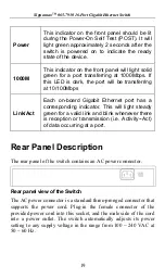
Страница 19: ...oard Gigabit Ethernet port has a corresponding indicator This will light steady green for a valid link and blink whenever there is reception or transmission i e Activity Act of data occurring at a port Rear Panel Description The rear panel of the switch contains an AC power connector Rear panel view of the Switch The AC power connector is a standard three pronged connector that supports the power ...

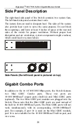
Страница 20: ...omponents might overheat which could lead to system failure Side Panels the left hand panel is pictured on top Gigabit Combo Ports In addition to the 16 10 100 1000 Mbps ports the Switch features two Mini GBIC Combo ports These two ports are 10 100 1000BaseT copper ports built in and Mini GBIC ports optional The two Mini GBIC port modules are plugged into the Switch Please note that the Mini GBIC ...

Страница 21: ...on Power On Package Contents Open the shipping carton of the Switch and carefully unpack its contents The carton should contain the following items One Gigabit Ethernet Switch One AC power cord The user s manual Mounting Kit two brackets and screws Four rubber feet with adhesive backing If any item is missing or damaged please contact your local Reseller for replacement ...

Страница 22: ...ugged in and secured to the AC power port Make sure that the Switch is allowed proper heat dissipation and adequate ventilation Leave at least 4 inches 10 cm of space at the front and rear of the Switch for ventilation Install the Switch in a fairly cool and dry place for the acceptable temperature and humidity operating ranges Install the Switch in a site free from strong electromagnetic field ge...

Страница 23: ...k The Switch can be mounted in a standard 19 rack Fasten the mounting brackets to the Switch using the screws provided With the brackets attached securely you can mount the Switch in a standard rack Power On Plug one end of the AC power cord into the power connector of the Switch and the other end into the local power source outlet After the Switch is powered on the LED indicators will momentarily...

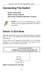
Страница 24: ...rts can support both MDI II and MDI X connections Switch To End Node End nodes include PCs routers and other network devices outfitted with a 10 100 or 1000 Mbps RJ 45 Ethernet Fast Ethernet Gigabit Ethernet ports An end node can be connected to the Switch via a twisted pair Category 3 4 or 5 or better UTP STP cable The end node can be connected to any of the ports of the Switch Switch connected t...

Страница 25: ...ns can be accomplished in a number of ways using a Standard Ethernet patch cable A 10BaseT hub or switch can be connected to the Switch via a twisted pair Category 3 4 or 5 UTP STP cable A 100BaseTX hub or switch can be connected to the Switch via a twisted pair Category 5 UTP STP cable A 1000BaseTX switch can be connected to the Switch via a twisted pair Category 5 or better UTP STP cable Switch ...

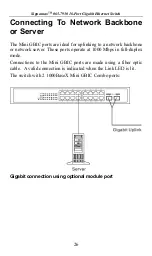
Страница 26: ...r uplinking to a network backbone or network server These ports operate at 1000 Mbps in full duplex mode Connections to the Mini GBIC ports are made using a fiber optic cable A valid connection is indicated when the Link LED is lit The switch with 2 1000BaseX Mini GBIC Combo ports Gigabit connection using optional module port ...

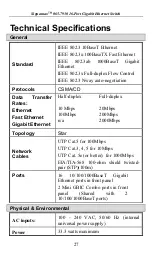
Страница 27: ...rnet Fast Ethernet Gigabit Ethernet Half duplex Full duplex 10 Mbps 20Mbps 100Mbps 200Mbps n a 2000Mbps Topology Star Network Cables UTP Cat 5 for 100Mbps UTP Cat 3 4 5 for 10Mbps UTP Cat 5e or better for 1000Mbps EIA TIA 568 100 ohm shield twisted pair STP 100m Ports 16 10 100 1000BaseT Gigabit Ethernet ports in front panel 2 Mini GBIC Combo ports in front panel Shared with 2 10 100 1000BaseT por...

Страница 28: ...o 95 RH non condensing Dimensions 324 mm x 231 mm x 44 mm 1U 19 inch rack mount width Weight 4 96 pounds 2 25 Kg EMI FCC Class A CE Mark C Tick Safety CSA International Performance Transmission Method Store and forward RAM Buffer 272 Kbytes per device Filtering Address Table 4K MAC address per device Packet Filtering Forwarding Rate Full wire speed for all connections 14 880 pps for 10M 148 809 pp...

Страница 29: ... Fax 46 0 293 228 89 Phone 49 81 35 9303 0 Http www aesp se E mail info aesp se JOTEC AESP AS NORWAY Telefon 23 14 17 00 Ordrefax 23 14 17 10 Karihaugveien 102 Postboks 50 Ellingsrudasen 1006 Oslo Norway Phone 47 23 14 1700 Fax 47 23 14 1710 Http www jotec no E mail jotec jotec no AESP Russia RUSSIA Kronshtadtsky Blv 125499 Moscow Russia Phone 7 095 456 0704 Phone 7 095 456 0344 Fax 7 095 454 3040...

Отзывы: