SC5312A Operating & Programming Manual
Rev 1.0.2
10
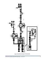
The RF attenuators provide attenuation when required. RF ATTEN#1 attenuation should be stepped up as
the signal power at the RF port increases above -10 dBm. Nonlinear components of the signal such as
IMD3 and second order harmonics will increase in magnitude as the input signal increases; therefore the
user should exercise good judgment to determine when to use RF ATTEN#1. Do not over attenuate
because this will hurt the signal to noise ratio.
RF ATTEN#2 is used if the input signal needs further suppression to improve linearity. It should also be
used if RF AMP#1 is enabled to improve sensitivity, but, as a result, the level at the input of RF AMP#3
(always in the path) may be too high. Step up the attenuation of RF ATTEN#2 to ensure the system
(resulting from RF AMP#3) is not driven too hard. RF ATTEN#3 is used to control the level to the IQ
demodulator when RF AMP#2 is enabled (switched into the signal path).
There is also an auxiliary RF input to the device. This input is almost identical to the main RF input with
the exception of having an extra switch path. The intended use of this port is to allow the user a calibration
path without having to detach the device under test (DUT) already cabled to the main RF input port. The
user must perform in-situ equalization to remove IQ errors such as phase imbalance and quadrature gain
offsets that are inherent to the device. Providing this auxiliary path makes the task of characterizing the
system with and without a DUT present much easier.
There are nine low pass filters in the RF filter bank. These filters are automatically selected when the user
enters the operating frequency. These filters can also be selected manually. As with all filters there is
generally an amplitude roll-off as the frequency nears its 3 dB cutoff point so it is important to understand
that frequencies near to the cutoff point may experience a slightly faster roll-off of their IF bandwidth. A
typical 1 dB IF bandwidth (IQ) is about 160 MHz. The user may want to choose a higher frequency filter if
this becomes a problem. See the programming section in this manual for more details. The filters in both
the RF and LO filter banks are identical and are listed below.
Filter Number
1 dB Cutoff Frequency
0
400 MHz
1
500 MHz
2
650 MHz
3
1000 MHz
4
1400 MHz
5
2000 MHz
6
2825 MHz
7
3800 MHz
8
6000 MHz
LO Input Section
The SC5312
A requires an external RF signal as its “Local Oscillator”
(LO) for the frequency conversion
process. The external RF sign
al must be connected to the “LO i
n
”
port. The typical required input level is -
3 dBm to 3 dBm. These levels are required to sufficiently drive the IQ demodulator for good linearity
performance and conversion loss. The LO signal is conditioned through a bank of low-pass filters to reduce


