


41110555
Rev 1.0
November 01, 2017
33
Product Technical Specification
Detailed Interface Specifications
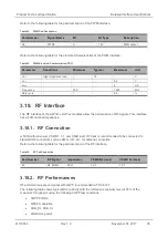
Refer to the following table for the electrical characteristics of the JTAG interface.
Table 29. JTAG Electrical Characteristics
Symbol
Parameter
Minimum
Typical
Maximum
Unit
F
tck
JTAG_TCK clock period
0.038 (TBC) 26 (TBC)
78 (TBC)
MHz
t
c2
JTAG_TCK clock period high
12 (TBC)
-
-
ns
t
c3
JTAG_TCK clock period low
12 (TBC)
-
-
ns
t
c4
JTAG_TDI setup time to JTAG_TCK
12 (TBC)
-
-
ns
t
c5
JTAG_TDI hold time from JTAG_TCK 10 (TBC)
-
-
ns
t
c6
JTAG_TDO valid before JTAG_TCK
low-end
-
0 (TBC)
-
s
t
c7
JTAG_TDO valid after JTAG_TCK
high begin
-
20 (TBC)
-
ns
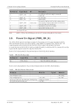
Figure 7.
JTAG Timing Waveform
3.15. Wake Up Signal (WAKE-UP)
The AirPrime HL77xx modules provide
one WAKE-UP signal.
The WAKE-UP signal is used to wake the system up from ultra-low power modes (from OFF or Sleep
modes, FAST_SHUTDOWN, or after a software power off). This signal should be set to high level
(external 1.8V) for at least (TBD) ms until the system is active to wake the module up from these
modes.
The system will not be allowed to go into ultra-low or off mode for as long as this signal is kept high.
By default, the software waits for a high state to wake-up.
Note:
The module has an embedded pull-down on this signal. After a power off mode, the only way to
restart the module is to perform a hardware power off then power on if this signal is not used.
Refer to the following table for the pad description of the WAKE-UP interface.
Table 30. WAKE-UP Pad Description
Pad Number
Signal Name
I/O
I/O Type
Description
19
WAKE-UP
I
1.8V
WAKE-UP


