s
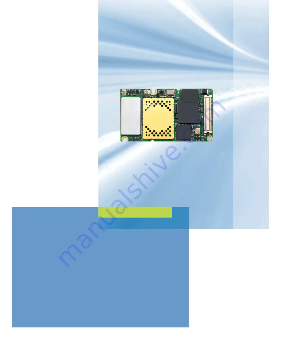
XT65/XT75 Siemens Cellular Engine
Version:
00.130
DocId:
XT65_XT75_HO_v00.130
Supported Products:
XT65, XT75
Hardware Interface Overview
Страница 1: ...s XT65 XT75 Siemens Cellular Engine Version 00 130 DocId XT65_XT75_HO_v00 130 Supported Products XT65 XT75 Hardware Interface Overview ...
Страница 2: ...ons or serious discrepancies in results Furthermore all safety instructions regarding the use of mobile technical systems including GSM products which also apply to cellular phones must be fol lowed Siemens AG customers using or selling this product for use in any applications do so at their own risk and agree to fully indemnify Siemens for any damages resulting from illegal use or resale To the m...
Страница 3: ... Types 22 4 3 Antenna Connector 23 5 GPS Antenna Interface 27 5 1 Antenna Installation 27 5 2 GPS Antenna 28 6 Electrical Reliability and Radio Characteristics 29 6 1 Absolute Maximum Ratings 29 6 2 Operating Temperatures 30 6 3 Storage Conditions 31 6 4 Reliability Characteristics 32 6 5 Pin Assignment and Signal Description 33 6 6 Power Supply Ratings 43 7 Mechanics 44 7 1 Mechanical Dimensions ...
Страница 4: ...or and recommended plugs 24 Table 9 Ordering information for Hirose U FL Series 26 Table 10 GPS antenna Active versus Passive 28 Table 11 Absolute maximum ratings 29 Table 12 Board temperature 30 Table 13 Ambient temperature according to IEC 60068 2 without forced air circulation 30 Table 14 Charging temperature 30 Table 15 Storage conditions 31 Table 16 Summary of reliability test conditions 32 T...
Страница 5: ...re 6 U FL R SMT connector with U FL LP 066 plug 24 Figure 7 Specifications of U FL LP V 040 01 plug 25 Figure 8 GPS antenna connector placement 27 Figure 9 GPS antenna pad placement 27 Figure 10 Pin assignment component side of XT65 XT75 33 Figure 11 XT65 XT75 top view 44 Figure 12 Dimensions of XT65 XT75 all dimensions in mm 45 Figure 13 Mating board to board connector 53748 0808 on application 4...
Страница 6: ...t the document both modules are generally referred to as XT65 XT75 1 1 Related Documents 1 XT65 AT Command Set 00 130 XT75 AT Command Set 00 130 2 XT65 XT75 Release Notes 00 130 3 DSB75 Support Box Evaluation Kit for Siemens Cellular Engines 4 Application Note 02 Audio Interface Design for GSM Applications 5 Application Note 07 Rechargeable Lithium Batteries in GSM Applications 6 Application Note ...
Страница 7: ...ean Conformity CHAP Challenge Handshake Authentication Protocol CPU Central Processing Unit CS Coding Scheme CSD Circuit Switched Data CTS Clear to Send DAC Digital to Analog Converter DAI Digital Audio Interface dBm0 Digital level 3 14dBm0 corresponds to full scale see ITU G 711 A law DCE Data Communication Equipment typically modems e g Siemens GSM engine DCS 1800 Digital Cellular System also re...
Страница 8: ...ization ITU International Telecommunications Union kbps kbits per second LED Light Emitting Diode Li Ion Li Lithium Ion Li battery Rechargeable Lithium Ion or Lithium Polymer battery Mbps Mbits per second MMI Man Machine Interface MO Mobile Originated MS Mobile Station GSM engine also referred to as TE MSISDN Mobile Station International ISDN number MT Mobile Terminated NTC Negative Temperature Co...
Страница 9: ...hort Message Service SPI Serial Peripheral Interface SRAM Static Random Access Memory TA Terminal adapter e g GSM engine TDMA Time Division Multiple Access TE Terminal Equipment also referred to as DTE Tx Transmit Direction UART Universal asynchronous receiver transmitter URC Unsolicited Result Code USB Universal Serial Bus USSD Unstructured Supplementary Service Data VSWR Voltage Standing Wave Ra...
Страница 10: ...ctive 1999 5 EC The product is labeled with the CE conformity mark 89 336 EC Directive on electromagnetic compatibility 73 23 EC Directive on electrical equipment designed for use within certain voltage limits Low Voltage Directive 95 94 EC Automotive EMC directive 2002 95 EC Directive of the European Parliament and of the Council of 27 Jan uary 2003 on the restriction of the use of certain hazard...
Страница 11: ...0MHz 6GHz Products intended for sale on European markets EN 50360 Product standard to demonstrate the compliance of mobile phones with the basic restrictions related to human exposure to electromagnetic fields 300MHz 3GHz IMPORTANT Manufacturers of portable applications based on XT65 XT75 modules are required to have their final product cer tified and apply for their own FCC Grant and Industry Can...
Страница 12: ...cian or the manufacturer of the device to verify that the equipment is properly shielded Pacemaker patients are advised to keep their hand held mobile away from the pacemaker while it is on Switch off the cellular terminal or mobile before boarding an aircraft Make sure it cannot be switched on inadvertently The operation of wireless appliances in an aircraft is forbidden to prevent interference w...
Страница 13: ...le must be switched on and in a service area with adequate cellular signal strength Some networks do not allow for emergency calls if certain network services or phone features are in use e g lock functions fixed dialing etc You may need to deactivate those features before you can make an emergency call Some networks require that a valid SIM card be properly inserted in the cellular terminal or mo...
Страница 14: ... maximum limits According to Release 99 the max imum output power in a multislot configuration may be lower The nominal reduc tion of maximum output power varies with the number of uplink timeslots used and amounts to 3 0dB for 2Tx 4 8dB for 3Tx and 6 0dB for 4Tx Power supply 3 3V to 4 5V Ambient operating temperature according to IEC 60068 2 Normal operation 30 C to 65 C Restricted operation 30 C...
Страница 15: ...verage Cold start 34s average Sensitivity Active antenna Aquisition sensitivity 141dBm Tracking sensitivity 158dBm At antenna connector Aquisition sensitivity 139dBm Tracking sensitivity 156dBm General Receiver 16 channel L1 1575 42 MHz GPS part controlled by GSM baseband controller Java engine or via application ASC0 Software AT commands AT Hayes GSM 07 05 and 07 07 Siemens AT commands for RIL co...
Страница 16: ...us Fixed bit rates 300 bps to 460 800 bps Autobauding 1 200 bps to 460 800 bps RTS0 CTS0 and XON XOFF flow control Multiplex ability according to GSM 07 10 Multiplexer Protocol USB Supports a USB 2 0 Full Speed 12Mbit s slave interface I2 C I2 C bus for 7 bit addressing and transmission rates up to 400kbps Programma ble with AT SSPI command Alternatively all pins of the I C interface are configura...
Страница 17: ...grammable as GPIO Programming is done via AT commands Alternatively GPIO pin10 is configurable as pulse counter Pulse counter Pulse counter for measuring pulse rates from 0 to 1000 pulses per second If the pulse counter is active the GPIO10 pin is not available DAC output Digital to Analog Converter which can provide a PWM signal Phonebook SIM and phone Evaluation kit DSB75 DSB75 Evaluation Board ...
Страница 18: ...rd to board connector that connects to the external application and incorporates several sub interfaces power supply charger interface SIM interface serial interface ASC0 serial interface USB serial interface I C SPI two analog audio interfaces digital audio interface DAI 10 lines GPIO interface as well as status and control lines IGT EMERG_RST PWR_IND SYNC for details see Chapter 2 and Section 6 ...
Страница 19: ...n depends on network settings e g power control level uplink downlink data rates GPRS configuration e g used multislot set tings and reduction of maximum output power POWER DOWN Normal shutdown after sending the AT SMSO command Only a voltage regulator is active for powering the RTC Software is not active Interfaces are not accessible Operating voltage connected to BATT remains applied Airplane mo...
Страница 20: ...roaches to connecting the antenna Recommended approach U FL R SMT antenna connector from Hirose assembled on the component side of the PCB Figure 1 GSM antenna connector placement See Section 4 3 for connector details Antenna pad and grounding plane placed on the bottom side See Section 4 2 The U FL R SMT connector has been chosen as antenna reference point ARP for the Siemens reference equipment ...
Страница 21: ...rence point ARP for the Siemens XT65 XT75 type approval The antenna pad is provided only as an alternative option which can be used for example if the recommended Hirose connection does not fit into your antenna design Please ensure that the antenna pad does not come into contact with the holding device or any other components of the host application It needs to be surrounded by a restricted area ...
Страница 22: ... standards of good engineering practice for soldering Be sure to solder the antenna core to the pad and the shielding of the coax cable to the ground plane of the module next to the antenna pad The direction of the cable is not relevant from the electrical point of view XT65 XT75 material properties XT65 XT75 PCB FR4 Antenna pad Gold plated pad 4 2 1 Suitable Cable Types For direct solder attachme...
Страница 23: ...DC to 3GHz Mechanical characteristics Female contact holding force 0 15N min Measured with a 0 475 pin gauge Repetitive operation Contact resistance Center 25mΩ Outside 15mΩ 30 cycles of insertion and disen gagement Vibration No momentary disconnections of 1µs No damage cracks and looseness of parts Frequency of 10 to 100Hz single amplitude of 1 5mm acceleration of 59m s2 for 5 cycles in the direc...
Страница 24: ...nector with U FL LP 066 plug Temperature cycle No damage cracks and looseness of parts Contact resistance Center 25mΩ Outside 15mΩ Temperature 40 C 5 to 35 C 90 C 5 to 35 C Time 30min within 5min 30min within 5min Salt spray test No excessive corrosion 48 hours continuous exposure to 5 salt water Table 8 Material and finish of U FL R SMT connector and recommended plugs Part Material Finish Shell P...
Страница 25: ...nary In addition to the connectors illustrated above the U FL LP V 040 01 version is offered as an extremely space saving solution This plug is intended for use with extra fine cable up to 0 81mm and minimizes the mating height to 2mm See Figure 46 which shows the Hirose datasheet Figure 7 Specifications of U FL LP V 040 01 plug ...
Страница 26: ... FL Series Item Part number HRS number Connector on XT65 XT75 U FL R SMT CL331 0471 0 10 Right angle plug shell for 0 81mm cable U FL LP 040 CL331 0451 2 Right angle plug for 0 81mm cable U FL LP V 040 01 CL331 053 8 01 Right angle plug for 1 13mm cable U FL LP 068 CL331 0452 5 Right angle plug for 1 32mm cable U FL LP 066 CL331 0452 5 Extraction jig E FL LP N CL331 04441 9 ...
Страница 27: ...s XT65 XT75 offers two alternative approaches to connecting the antenna Recommended approach U FL R SMT antenna connector from Hirose assembled on the component side of the PCB The GPS antenna connector is the same as for the GSM antenna connector For details see Section 5 3 Figure 8 GPS antenna connector placement Antenna pad and grounding plane placed on the bottom side of the PCB For some notes...
Страница 28: ... you are not an expert in RF designs you should implement an active antenna setup and place the antenna away from any emitting circuits Table 10 GPS antenna Active versus Passive Active Antenna Passive Antenna Active antenna connected to the GPS module Passive patch antennas or quadrifilar dipole antennas con nected with a microcoax to the GPS module A wide range of active patch or quadrifilar dip...
Страница 29: ...mited according to Table 11 Table 11 Absolute maximum ratings Parameter Min Max Unit Peak current of power supply 3 2 A Supply voltage BATT 0 3 5 5 V Voltage at digital pins in POWER DOWN mode 0 3 0 3 V Voltage at digital pins in normal operation 0 3 3 05 or VEXT 0 3 V Voltage at analog pins in POWER DOWN mode 0 3 0 3 V Voltage at analog pins VMIC on1 1 For normal operation the voltage at analog p...
Страница 30: ...0 C Table 13 Ambient temperature according to IEC 60068 2 without forced air circulation Parameter Min Typ Max Unit Operating temperature range 30 25 65 C Restricted operation with VBATT 3 8V 70 C Restricted operation1 1 Restricted operation allows normal mode speech calls or data transmission for limited time until automatic thermal shutdown takes effect For operating the XT75 65 above an expecte...
Страница 31: ...ative Low High Condens 10 90 at 30 C 90 100 at 30 C ETS 300 019 2 1 T1 2 IEC 68 2 56 Cb ETS 300 019 2 1 T1 2 IEC 68 2 30 Db Air pressure Low High 70 106 kPa IEC TR 60271 3 1 1K4 IEC TR 60271 3 1 1K4 Movement of surrounding air 1 0 m s IEC TR 60271 3 1 1K4 Water rain dripping icing and frosting Not allowed Radiation Solar Heat 1120 600 W m2 ETS 300 019 2 1 T1 2 IEC 68 2 2 Bb ETS 300 019 2 1 T1 2 IE...
Страница 32: ... 3 axes DIN IEC 68 2 6 Shock half sinus Acceleration 500g Shock duration 1msec 1 shock per axis 6 positions x y and z DIN IEC 68 2 27 Dry heat Temperature 70 2 C Test duration 16h Humidity in the test chamber 50 EN 60068 2 2 Bb ETS 300 019 2 7 Temperature change shock Low temperature 40 C 2 C High temperature 85 C 2 C Changeover time 30s dual chamber system Test duration 1h Number of repetitions 1...
Страница 33: ..._IND 78 4 GND Do not use 77 5 GPIO10 GPIO9 76 6 GPIO8 SPICS 75 7 SPIDI GPIO4 74 8 GPIO7 GPIO3 73 9 GPIO6 GPIO2 72 10 GPIO5 GPIO1 71 11 I2CCLK_SPICLK I2CDAT_SPIDO 70 12 VUSB_IN USB_DP 69 13 DAI5 USB_DN 68 14 ISENSE VSENSE 67 15 DAI6 VMIC 66 16 CCCLK EPN2 65 17 CCVCC EPP2 64 18 CCIO EPP1 63 19 CCRST EPN1 62 20 CCIN MICN2 61 21 CCGND MICP2 60 22 DAI4 MICP1 59 23 DAI3 MICN1 58 24 DAI2 AGND 57 25 DAI1 ...
Страница 34: ...nnected If unused keep pin open BATT_TEMP I Connect NTC with RNTC 10kΩ 25 C to ground Batterytemperaturemeasurement via NTC resistance NTC should be installed inside or near battery pack to enable proper charging and deliver temperature values If unused keep pin open ISENSE I VImax 4 65V ΔVImax to VBATT 0 3V at normal condition Connect ISENSE directly at the shunt for current measurement If unused...
Страница 35: ...n low by an open drain or open collector driver Emer gency reset EMERG_RST I Internal pull up RI 5kΩ VILmax 0 2V at Imax 0 5mA VOHmin 1 75V VOHmax 3 05V Signal ______ Pull down 10ms Reset or shut down in case of emergency Pull down and release EMERG_RST Then activating IGT for 400ms will reset XT65 XT75 If IGT is not activated for 400ms XT65 XT75 switches off Data stored in the volatile memory wil...
Страница 36: ...ing handover b Driving a status LED to indicate different operating modes of XT65 XT75 The LED must be installed in the host application To select a or b use the AT SSYNC command If unused keep pin open RTC backup VDDLP I O RI 1kΩ VOmax 4 5V VBATT 4 2V VO 3 3V at IO 500µA VBATT 0V VI 2 4V 4 5V at Imax 25µA If unused keep pin open ASC0 Serial interface RXD0 O VOLmax 0 2V at I 2mA VOHmin 2 55V at I ...
Страница 37: ... holder All signals of SIM interface are protected against ESD with a spe cial diode array Usage of CCGND is mandatory CCRST O RO 47Ω VOLmax 0 25V at I 1mA VOHmin 2 5V at I 0 5mA VOHmax 2 95V CCIO I O RI 4 7kΩ VILmax 0 75V VILmin 0 3V VIHmin 2 1V VIHmax CCVCCmin 0 3V 3 05V RO 100Ω VOLmax 0 3V at I 1mA VOHmin 2 5V at I 0 5mA VOHmax 2 95V CCCLK O RO 100Ω VOLmax 0 3V at I 1mA VOHmin 2 5V at I 0 5mA V...
Страница 38: ...O 100Ω VOLmax 0 3V at I 1mA VOHmin 1 45V at I 0 5mA VOHmax 1 90V CCVCC O VOmin 1 70V VOtyp 1 80V VOmax 1 90V IOmax 20mA CCGND Ground I2 C inter face I2CCLK _SPICLK O VOLmax 0 2V at I 2mA VOHmin 2 55V at I 0 5mA VOHmax 3 05V I2 C interface is only available if the two pins are not used as SPI inter face I2CDAT is configured as Open Drain and needs a pull up resistor in the host application Accordin...
Страница 39: ...er volt age Range VCRSmin 1 5V VCRSmax 2 0V Driver Output Resistance ZDRVtyp 32Ohm USB_DP I O Digital Audio interface DAI0 USC0 I O VOLmax 0 2V at I 2mA VOHmin 2 55V at I 0 5mA VOHmax 3 05V VILmax 0 8V VIHmin 2 15V VIHmax VEXTmin 0 3V 3 05V DAI0 DAI6 are configurable as PCM interface DAI1 USC1 I O DAI2 USC2 I O DAI3 USC3 I O DAI4 USC4 I O DAI5 USC5 I O DAI6 USC6 I O General Purpose Input Out put G...
Страница 40: ... 0 5mV Inputs used for measuring exter nal voltages In the range of 0mV to 2400mV Use the command AT SRADC to select analog inputs ADC1_IN or ADC2_IN to set the measurement mode and read out the results The values are indicated in mV ADC1_IN and ADC2_IN are inter nally multiplexed through analog switch Important For restrictions during SLEEP mode see 1 ADC2_IN I Digital Analog Converter DAC_OUT O ...
Страница 41: ...n directly operate an 8 Ohm loudspeaker If unused keep pins open EPN1 O MICP1 I Differential Line Input Configuration Apply external bias of 1 5V at MICN1 Full Scale Input Voltage 1 6 Vpp 0dBm0 Input Voltage 1 1 Vpp Measurement conditions Audio mode 5 SNFI 0 32767 PGA 0dB Ri 100 kOhm typical Balanced or single ended micro phone or line input with external feeding circuit using VMIC and AGND If unu...
Страница 42: ...here are three protection possibilities Use an RC combination for current limitation Advantages Lowest current consumption at SLEEP Mode small component count high input resistance Disadvantages Lower input resistance at Sleep Mode 100k only Use the AT SNFM 1 command to enable the ADC supply continuously Advantages No additional component components needed Disadvantages Higher current consumption ...
Страница 43: ...tage on BATT w o INIT show increased POWER DOWN supply current 60 120 µA Average standby supply current2 GPS off 2 Additional conditions SLEEP and IDLE mode measurements started 5 minutes after switching ON the module or after mode transition Averaging times SLEEP mode 3 minutes IDLE mode 1 5 minutes Communication tester settings no neighbor cells no cell reselection USB interface disabled SLEEP m...
Страница 44: ...2 Confidential Preliminary 7 Mechanics 7 1 Mechanical Dimensions of XT65 XT75 Figure 11 shows the top view of XT65 XT75 and provides an overview of the board s mechanical dimensions For further details see Figure 12 Length 55 00mm Width 33 90mm Height 3 15mm Figure 11 XT65 XT75 top view Pin1 Pin80 ...
Страница 45: ...T65 XT75 Hardware Interface Overview 7 1 Mechanical Dimensions of XT65 XT75 s XT65_XT75_HO_v00 130 Page 45 of 67 2006 10 12 Confidential Preliminary Figure 12 Dimensions of XT65 XT75 all dimensions in mm ...
Страница 46: ...selected screws and distance sleeves for 3mm stacking height can be found in Section 9 2 When using the two small holes take care that the screws are inserted with the screw head on the bottom of the XT65 XT75 PCB Screws for the large holes can be inserted from top or bottom For proper grounding it is strongly recommended to use large ground plane on the bottom of board in addition to the five GND...
Страница 47: ...0mm see Figure 14 for details Supplier Molex http www molex com Table 19 Technical specifications of Molex board to board connector Parameter Specification 80 pin B2B connector Electrical Number of Contacts 80 Contact spacing 0 5mm 020 Voltage 50V Rated current 0 5A max per contact Contact resistance 50mΩ max per contact Insulation resistance 100MΩ Dielectric Withstanding Voltage 500V AC for 1 min...
Страница 48: ...age 48 of 67 2006 10 12 Confidential Preliminary Mating connector types for the customer s application offered by Molex Figure 13 Mating board to board connector 53748 0808 on application 53748 0808 SlimStack Plug 3mm stacking height see Figure 15 for details 53916 0808 SlimStack Plug 4mm stacking height ...
Страница 49: ...75 Hardware Interface Overview 7 3 Board to Board Application Connector s XT65_XT75_HO_v00 130 Page 49 of 67 2006 10 12 Confidential Preliminary Figure 14 Molex board to board connector 52991 0808 on XT65 XT75 ...
Страница 50: ... Hardware Interface Overview 7 3 Board to Board Application Connector s XT65_XT75_HO_v00 130 Page 50 of 67 2006 10 12 Confidential Preliminary Figure 15 Mating board to board connector 53748 0808 on application ...
Страница 51: ... XT65 XT75 consists of the following components Siemens XT65 XT75 cellular engine Development Support Box DSB75 SIM card reader integrated on DSB75 U FL R SMT antenna connector and U FL LP antenna cable Handset type Votronic HH SI 30 3 V1 1 0 Li Ion battery PC as MMI Figure 16 Reference equipment for Type Approval PC Power supply SIM RS 232 DSB75 Handset Li Ion battery GSM module Flex cable 100mm ...
Страница 52: ...ting Contains FCC ID QIP XT65 resp Contains FCC ID QIP XT75 IMPORTANT Manufacturers of portable applications incorporating XT65 XT75 modules are required to have their final product certified and apply for their own FCC Grant and Industry Canada Certificate related to the specific portable mobile This is mandatory to meet the SAR requirements for portable mobiles see Section 1 3 2 for detail Chang...
Страница 53: ...8830 A100 Customer IMEI mode Siemens Ordering number L36880 N8831 A100 Siemens Car Kit Portable Siemens Siemens ordering number L36880 N3015 A117 DSB75 Support Box Siemens Siemens ordering number L36880 N8811 A100 Votronic Handset VOTRONIC Votronic HH SI 30 3 V1 1 0 VOTRONIC Entwicklungs und Produktionsgesellschaft für elek tronische Geräte mbH Saarbrücker Str 8 66386 St Ingbert Germany Phone 49 0...
Страница 54: ...rong Singapore Phone 65 268 6868 Fax 65 265 6044 Molex Japan Co Ltd Yamato Kanagawa Japan Phone 81 462 65 2324 Fax 81 462 65 2366 Table 22 Hirose sales contacts subject to change Hirose Ltd For further information please click http www hirose com Hirose Electric U S A Inc 2688 Westhills Court Simi Valley CA 93065 U S A Phone 1 805 522 7958 Fax 1 805 522 3217 Hirose Electric GmbH Zeppelinstrasse 42...
Страница 55: ... list remains preliminary although it is going to be updated in later versions of this document 9 2 1 Fasteners from German Supplier ETTINGER GmbH Sales contact ETTINGER GmbH http www ettinger de main cfm Phone 4981 04 66 23 0 Fax 4981 04 66 23 0 The following tables contain only article numbers and basic parameters of the listed components For further detail and ordering information please contac...
Страница 56: ...pping1 Length 3 0mm Material Polyamide 6 6 Surface Black Internal diameter 2 2mm External diameter 4 0mm Flammability rating UL94 HB 1 2 spacers are delivered with DSB75 Support Board Article number 05 11 209 Threaded Stud M2 5 M2 Type E External thread at both ends Length 3 0mm Material Stainless steel X12CrMoS17 Thread 1 Length M2 5 6 0mm Thread 2 Length M2 8 0mm Width across flats 5 Recess yes ...
Страница 57: ...rew M21 DIN 84 ISO 1207 Length 8 0mm Material Steel 4 8 Surface Zinced A2K Thread M2 Head diameter D 3 8mm Head height 1 30mm Type Slotted cheese head screw 1 2 screws are delivered with DSB75 Support Board Article number 01 14 141 Screw M2 DIN 84 ISO 1207 Length 10 0mm Material Steel 4 8 Surface Zinced A2K Thread M2 Head diameter D 3 8mm Head height 1 30mm Type Slotted cheese head screw ...
Страница 58: ...pment s XT65_XT75_HO_v00 130 Page 58 of 67 2006 10 12 Confidential Preliminary Article number 02 10 011 Hexagon Nut1 DIN 934 ISO 4032 Material Steel 4 8 Surface Zinced A2K Thread M2 Wrench size 4 Thickness L 1 6mm Type Nut DIN UNC DIN934 1 2 nuts are delivered with DSB75 Support Board ...