


Installation and connection
en
19
■
Directly into the open air
Route the exhaust air duct directly
into the open air via an exhaust air
pipe through an open window.
Example: pipe connection - inside
diameter = 100 mm, flexible pipe,
corrugated
■
Through a wall box into chimneys or
ventilation shafts
Notes
– It is not permitted to connect the
exhaust air duct to chimneys
which are connected to gas or
coal-fired ovens/cookers or gas-
fired heating systems.
– If the appliance is being
connected to a moisture-
insulated ventilation shaft the
reponsible chimney sweep must
be informed and the approval of
the local building department
(building supervision office) or
the owner of the building must be
obtained.
Caution!
Risk of poisoning
If other appliances are operated in
the room where the appliance is
installed or in adjoining rooms, e.g.
gas-fired heating systems, gas-fired
boilers, coal-fired ovens connected
to a chimney, or open fireplaces, a
vacuum may be created, leading to
waste gases being sucked back.
Note:
In every case, have safe
operation confirmed by the
responsible chimney sweep, boiler
engineer, ventilation specialist, etc.
Installing more than one dryer
Up to 7 exhaust air dryers can be
connected to an intercepting pipe with a
smooth internal wall.
Note:
The following points must be
observed:
■
It is imperative that there are drain
check valves in the interception pipe
for every dryer. These valves prevent
the moist exhaust air from flowing
back into the washing and drying
room through dryers which are not in
operation.
■
The outlet for the exhaust air must
be arranged/routed in such way as
to prevent any additional
backpressure (e.g. from a direct
ingress of wind) on the escaping
exhaust air.
■
In every case, have safe operation
confirmed by the responsible
ventilation engineer/installer.
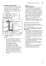
A = curved pipe (R = 300 mm) 7
B = straight piece (1.5 m)
18
C = curved pipe (R = 100 mm) 10
D = straight piece (0.5 m)
6
Total pressure loss
41
Содержание WT34A2L7DN
Страница 39: ...6 ...


