


UTMC OTU/MOVA Handbook
667/HB/31601/000
Page 28
Issue 5
a small piece of film inserted between it and the associated holder. This must be pulled
out to enable the battery to function.
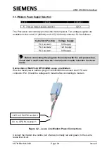
Watchdog link
Ensure the watchdog link is installed across pins 1 and 2 of PL6 on the Processor card.
4.3 INSTALLATION INTRODUCTION
9
Install unit and connect safety earth lead to
cabinet earth point
A standard hardware installation, in terms of location and cable routing, is not possible,
as different manufacturer’s cabinets differ in size, model and occupancy. Use of the
following guidelines provides a level of standardisation.
4.4 HARDWARE INSTALLATION
4.4.1 General Installation
The unit assembly is a 3U extended unit, requiring 192mm of 3U rack space. This,
together with configurable cableforms, provides sufficient flexibility to install the
hardware in most enclosures, in one of the three positions described below. Also see
section 5.5 for details of part numbers.
(a)
The unit may occupy space in a suitable rack with sufficient space in a cabinet.
See the bottom half of drawing 667/GA/26577/000, referenced in Appendix A.
(b)
If no suitable rack space exists as in (a), the unit rack mounting facility can be
used (the M6 screws in rack angles) to allow the unit installation. See the top half
of 667/GA/26577/000 drawing, referenced in Appendix A.
(c)
If options (a) and (b) are not available, then an alternative suitable method
should be adopted, with the collaboration of Poole Engineering or use an
Additional Outercase. If the Additional Outercase method is used, then additional
installation work is required (see section 5.7 of the Gemini
2
Traffic Outstation
Handbook for details).
(d)
If the unit is to be mounted in such a way that the ‘Battery Warning Label’ is
visible on the top of the unit then the following modifications are necessary. This
is to ensure that the battery is not operating upside down.
Ensure the Battery Fuse is
not installed
Temporarily dismantle the PSU
Remove the metal cover (NB Do not remove any modem attached
to this cover)
Disconnect the battery connection leads
Cut away the Battery retention tie wraps
Rotate the battery through 180 degrees