background image

A5E32243983

Le Probe – INSTRUCTIONS DE SERVICE

Page 3

mmm

mm

Fr

a

n

ç

a

is

Connexions

Entrée de câble

Synoptique

Col sanitaire 4"

119 mm (4.68")

97 mm (3.83")

Dimensions approximatives

Le Probe

collier de 
serrage*

vis de 
serrage

virole

réservoir

• Installer Le Probe sur la virole 

(ou col évasé) du réservoir.

• Serrer à l’aide du collier de 

serrage.

• Serrer la vis de serrage.

Note : 

L’intérieur du col doit 

être lisse, sans points de 
soudure, bavures ou saillies.

*fourni avec Le Probe

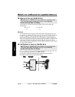
A.S’assurer que le couvercle soit fermé, puis appuyer sur les deux 

pré-perçages pour les retirer.

B. Déserrer la vis de fixation et ouvrir le couvercle.
C. Installer le câble de liaison à l’intérieur de l’unité Probe.
D. Connecter la boucle.
E. Fermer le couvercle et serrer la vis (1,1 -1,7 N-m (10 -15 in-lb).

Le Probe

équipement en 

boucle

Содержание THE PROBE

Страница 1: ...Ultrasonic Transmitters Operating Instructions 03 2013 THE PROBE ...

Страница 2: ...und version and in electronic version We encourage users to purchase authorized bound manuals or to view electronic versions as designed and authored by Siemens Milltronics Process Instruments Siemens Milltronics Process Instruments will not be responsible for the contents of partial or whole reproductions of either bound or electronic versions While we have verified the contents of this manual fo...

Страница 3: ... and agitator blades in motion The time for the pulse to travel to the material and back is temperature compensated and then converted into distance for display mA output Installation Environmental The Probe should be mounted in an area that is within the temperature range specified and that is suitable to the housing rating and materials of construction The front lid should be accessible to allow...

Страница 4: ...erting The Probe into its mounting hole ensure that the threads are of the same type to avoid damaging The Probe threads The Probe can be fitted with the optional 75 mm 3 flange adapter for mating to 3 ANSI DIN 65PN10 and JIS 10K3B flanges The Probe optional flange adapter hinged lid 117 mm 4 6 cable entry knock out 87 mm 3 4 ø 61 mm 2 4 7 mm 0 3 84 mm 3 3 max electronics mounting thread sensor 53...

Страница 5: ...nk s sanitary ferrule secure mating by surrounding the joint with the clamp tighten adjusting wing nut Note Inside of sanitary ferrule must be smooth free of burrs seams or ridges supplied with the Probe A With lid closed remove cable entry knock out on either side as required B Open lid by loosening the lid screw C Run cable to The Probe D Connect loop wiring E Close lid Tighten screw to 1 1 to 1...

Страница 6: ...safe apparatus including interconnecting wiring must be equal to or less than the capacitance and inductance which can be safely connected to associated apparatus FM CSA reference drawing 1 8600016Z DX A Approved dust tight and water tight conduit seals are required for Class II Div 1 Gr E F G and outdoor Type 4 NEMA 4X IP65 locations The maximum voltage of the non intrinsically safe apparatus mus...

Страница 7: ...706 4 3 1 2 STAHL 9002 13 280 110 00 3 4 1 2 STAHL 9001 51 280 110 14 3 4 2 Note Power supply input is reverse polarity protected Safe Area Hazardous Area load 4 to 20 mA 20 to 35 V DC supply MTL 3041 20 to 35 V DC 4 to 20 mA seeterminal connection table Safe Area Hazardous Area 4 to 20 mA seeterminal connection table 4 to 20 mA MTL 2441 120V 240 V load N L2 ...

Страница 8: ...The certification of this equipment relies upon the following materials used in its construction BF Goodrich PVC GEON 85856 enclosure and lid material ETFE transducer PVDF alternative transducer Master Bond Polysulphide EP21LPT or Dow Corning 3 4207 encapsulant transducer Emmerson and Cummings Stycast 2075 encapsulant electronics If the equipment is likely to come into contact with aggressive subs...

Страница 9: ...ortional span high level 20 mA high level 4 mA low level 4 mA low level 20 mA Press 4 Press 4 again 4 mA calibration new 4mA calibration calibration invalid if retry With The Probe correctly installed or aimed at a wall 0 25 to 5 m away apply power The Probe starts up displaying the following program mode alphanumeric units LOE fault operation status 4 key 20 key It then defaults to the Run mode w...

Страница 10: ...n values can be selected where reference levels either from the material in the vessel or from a target cannot be provided This method can also be used to trim the output levels obtained by the Reference Method see page 7 To change the stored calibration value obtain the c 4 or c 20 display The calibration value may be increased by pressing the 20 key or decreased by pressing the 4 key When the di...

Страница 11: ...ter scrolling hold the key depressed during the calibration adjustment and release when desired value is obtained press 4 to decrease to new calibration value i e 0 45 m new calibration value 3 sec blanking stored blanking value i e 0 25 m press 20 to increase blanking i e 0 36 m Note For faster scrolling hold the key depressed during the blanking adjustment and release when desired value is obtai...

Страница 12: ...ill be able to keep up with rates of change If The Probe measurement cannot keep up with the rate of level change set the adjustment from 1 to 2 If The Probe still cannot keep up with the rate of level change set the adjustment option to 3 Avoid choosing an option that is too fast for your application agitator discrimination discriminates between agitator blades in motion and the material target s...

Страница 13: ...il safe timer obtain the FSt display Increase the waiting period by pressing the 20 key and decrease it by pressing the 4 key stopping when the desired value is displayed The display automatically reverts to the Run mode 6 sec Units The units of the measurement reading can be selected as follows 1 metres m factory setting 2 feet ft The selected units are also applicable to the Blanking adjustment ...

Страница 14: ...be is waiting for a valid echo before updating the measurement Probable causes are material or object in contact with sensor face The Probe is too close to the fill point The Probe is not perpendicular to the liquid surface change in level too fast measurement out of range foam on liquid surface high level of vibration in the mounting structure level inside the blanking zone The Waiting period has...

Страница 15: ...pensate over the operating range Display liquid crystal three 9 mm 0 35 digits for reading of distance between sensor face and material multisegment graphic for operation status mA Output range 4 to 20 mA span proportional or inversely proportional accuracy 0 25 of full scale resolution 3 mm 0 125 loading 600 ohms max loop load at 24 V DC supply cable Belden 8760 shielded twisted pair 28 AWG 0 75 ...

Страница 16: ... C TICK EMC performance available on request Intrinsically safe CSA FM intrinsically safe for Class I and II Div 1 GR A B C D E F G hazardous location ATEX II 1G BAS99ATEX1300 INMETRO DNV 12 0071X Ex ia IIC T4 Ga IP65 40 C Ta 60 C DNV OCP 0017 ABNT NBR IEC 60079 0 2008 e ABNT NBR IEC 60079 11 2009 ...

Страница 17: ...t zum Material und zurück ist temperaturkompensiert Sie wird für die Werte von Anzeige und mA Ausgang in einen Abstandswert umgewandelt Installation Umgebung Die Temperaturen am Einbauort dürfen die maximal zulässigen Temperaturwerte nicht überschrei ten Die Umgebung muss für die Gehäuseschutzart und den Werkstoff geeignet sein Der Probe ist so zu montieren dass der elektrische Anschluss die Kalib...

Страница 18: ...des Probe Gewindes zu vermeiden ist vor Einschrauben des Probe das Montagegewinde zu überprüfen damit es sich um denselben Gewindetyp handelt Optional ist die Lieferung eines 75 mm 3 Flanschadapters für 3 ANSI DIN 65PN10 und JIS 10K3B Flansche möglich The Probe Flansch adapter Option Klapp deckel 117 mm 4 6 Blind verschluss 87 mm 3 4 ø 61 mm 2 4 7 mm 0 3 84 mm 3 3 max Elektronik Montage gewinde Se...

Страница 19: ...rs Sorgen Sie für festen Sitz durch Anbringung der Klemmschelle um die Dichtung Ziehen Sie die Einstellmutter an Hinweis Die Innenseite des sanitären Tri Clamps muss glatt und frei von Graten Fugen oder Furchen sein mitgeliefert A Bei geschlossenem Deckel den vorgesehenen Blindverschluss entfernen B Schraube lösen und Deckel öffnen C Kabel einführen D Kabel für die Schleife anschließen E Deckel sc...

Страница 20: ...er gleich der Kapazität oder Induktivität sein welche gefahrlos an das zugeordnete Gerät angeschlossen werden kann FM CSA Bezugszeichnung 1 8600016Z DX A Für Standorte Klasse II Div 1 Gr E F G und im Außenbereich Typ 4 NEMA 4X IP65 sind zugelas sene staub und wasserdichte Leitungsverschlüsse erforderlich Die maximale Spannung eines nicht eigensicheren Betriebsmittels darf 250 V rms nicht überschre...

Страница 21: ...STAHL 9002 13 280 110 00 3 4 1 2 STAHL 9001 51 280 110 14 3 4 2 Hinweis Der Spannungseingang ist verpolungsgeschützt Sicherer Bereich Ex gefährdeter Bereich Bürde 4 bis 20 mA 20 bis 35 V DC Hilfs energie MTL 3041 20 to 35 V DC 4 bis 20 mA siehe Anschluss tabelle Sicherer Bereich Ex gefährdeter Bereich 4 bis 20 mA siehe Anschluss tabelle 4 bis 20 mA MTL 2441 120V 240 V Bürde N L2 ...

Страница 22: ...llerdokumentation eingefügt werden 7 Die Betriebsmittel Zulassung richtet sich nach folgenden verwendeten Werkstoffen BF Goodrich PVC GEON 85856 Material für Gehäuse und Deckel ETFE Sensor PVDF wahlweise für den Sensor Master Bond Polysulphid EP21LPT oder Dow Corning 3 4207 Vergussmaterial Sensor Emmerson and Cummings Stycast 2075 Vergussmaterial Elektronik Besteht die Wahrscheinlichkeit dass das ...

Страница 23: ...and 20 mA Max Füllstand 4 mA Min Füllstand 4 mA Min Füllstand 20 mA Taste 4 Taste 4 erneut drücken 4 mA Abgleich neuer 4 mA Abgleich Abgleich ungültig bei wiederholen Nach korrekter Installation des Probe oder Ausrichtung auf eine Wand in 0 25 bis 5 m Abstand wird die Versorgungsspannung zugeschaltet Bei Inbetriebnahme des Probe erscheint folgende Anzeige Programmiermodus alphanumerisch Einheit LO...

Страница 24: ...erte ist möglich wenn kein Referenzfüllstand vom zu messenden Material oder von einem Ziel geliefert werden kann Diese Methode erlaubt auch einen Feinabgleich der mit der Referenzmethode erhaltenen Werte siehe Seite 7 Um die programmierten Werte zu ändern ist die Anzeige c 4 oder c 20 aufzurufen Der Wert kann mit der Taste 20 erhöht und mit der Taste 4 verringert werden Drücken Sie die entsprechen...

Страница 25: ... zeigten Werte kann beschleunigt werden indem Sie die jeweilige Taste gedrückt halten bis der gewünschte Wert erreicht ist Taste 4 um den Wert zu verringern Bsp 0 45 m Neuer Kalibrierungswert 3 Sek Ausblendung Gespeicherter Ausblendungswert Bsp 0 25 m Taste 20 zur Erhöhung der Ausblendung Bsp 0 36 m Hinweis Der Durchlauf der angezeigten Werte kann beschleunigt werden indem Sie die jeweilige Taste ...

Страница 26: ...gkeit mit der der Probe auf Füllstandsänderungen reagiert Wenn der Probe nicht schnell genug auf Füllstandsänderungen reagiert stellen Sie den Wert von 1 auf 2 Ist dieser Wert immer noch nicht ausreichend so kann die Option 3 gewählt werden Es sollte jedoch vermieden werden einen für die Applikation zu hohen Wert zu programmieren Rührwerks ausblendung Unterscheidung zwischen der Schaufelbewegung e...

Страница 27: ...nzeige aufzurufen Der Wert kann mit der Taste 20 erhöht und mit der Taste 4 verringert werden Drücken Sie die entsprechende Taste solange bis der gewünschte Wert erreicht ist Die Anzeige kehrt automatisch in den Run Modus zurück 6 Sek Einheiten Die Messwerte können in folgenden Einheiten angezeigt werden 1 Meter m Werkseinstellung 2 Feet ft Die gewählte Einheit gilt auch für die Einstellung der Na...

Страница 28: ...sswert aktualisiert wird Mögliche Ursachen Material oder Zielobjekt hat Kontakt zum Sensor Der Probe ist zu nahe an der Befüllung angebracht Der Probe steht nicht senkrecht zur Flüssigkeitsoberfläche Füllstand ändert sich zu schnell Messwert außerhalb des Messbereichs Schaumbildung auf der Flüssigkeitsoberfläche Starke Vibrationen in der Montagestruktur Füllstand innerhalb der Nahbereichsausblendu...

Страница 29: ...atische Laufzeitkorrektur im Messbereich Anzeige LCD Flüssigkristall drei Stellen Höhe 9 mm 0 35 zur Anzeige des Abstands zwischen Sensorunterkante und zu messendem Material grafische Anzeige mit mehreren Feldern für Betriebszustand mA Ausgang Bereich 4 bis 20 mA Mess Spanne proportional oder umgekehrt proportional Genauigkeit 0 25 vom Messbereich Auflösung 3 mm 0 25 Bürde max 600 Ohm bei 24 V DC ...

Страница 30: ... CE C TICK EMV Bescheinigung auf Anfrage erhältlich Eigensicherheit CSA FM eigensicher für Klasse I II Div 1 GR A B C D E F G Ex gefährdeter Bereich ATEX II 1 G BAS99ATEX1300 INMETRO DNV 12 0071X Ex ia IIC T4 Ga IP65 40 C Ta 60 C DNV OCP 0017 ABNT NBR IEC 60079 0 2008 e ABNT NBR IEC 60079 11 2009 ...

Страница 31: ... eléctricos y aspas paletas de agitadores en movimiento El tiempo de ida y vuelta de cada impulso hacia y desde el medio es compensado en temperatura y se convierte en distancia su visualización en salida de mA y en actuación de relé Instalación Condiciones ambientales The Probe debe montarse en un área que no sobrepase los límites de temperatura especificados y que sea adecuada a las especificaci...

Страница 32: ...de que la rosca sea del mismo tipo que la del aparato para que ésta no sufra daños The Probe puede montarse con el adaptador opcional 75 mm 3 en bridas 3 ANSI DIN 65PN10 y JIS 10K3B The Probe Adaptador de brida opción Tapa abatible 117 mm 4 6 Entrada de cable 87 mm 3 4 ø 61 mm 2 4 7 mm 0 3 84 mm 3 3 máx Electrónica Rosca de montaje Sensor 53 mm 2 1 ø máx 279 mm 11 76 mm 2 9 Anillo de estanqueidad ...

Страница 33: ...pósito El sistema se fija con la abrazadera y Se aprieta la tuerca mariposa Nota La parte interior de la férula sanitaria debe ser lisa sin juntas peldaños o aristas Proporcionado con The Probe A Con la tapa cerrada se extrae el tope de la entrada de cable situado en el lado deseado B Se abre la tapa aflojando su tornillo C Se conecta el cable a The Probe D Se conecta el lazo de corriente E Se cie...

Страница 34: ...intrínseca y el cable de conexión deben ser inferiores o equivalentes a las capacitancias e inductancias que se conectarán sin riesgo al aparato relacionado FM CSA diagrama de referencia 1 8600016Z DX A Utilizar conductos aptos estancos al polvo y al agua para aplicaciones en zona Clase II Div 1 Gr E F G y para uso en exterior aplicaciones Tipo 4 NEMA 4X IP65 La máxima tensión de aparatos convenci...

Страница 35: ...06 4 3 1 2 STAHL 9002 13 280 110 00 3 4 1 2 STAHL 9001 51 280 110 14 3 4 2 Nota Protección del suministro eléctrico alimentación contra polaridad invertida Zona segura Zona peligrosa Carga 4 a 20 mA Alimentación 20 a 35 V DC MTL 3041 20 a 35 V DC 4 a 20 mA Ver tabla de conexiones Zona segura Zona Peligrosa 4 a 20 mA Ver tabla de conexiones 4 a 20 mA MTL 2441 120 V 240 V Carga N L2 ...

Страница 36: ...orcionada por el fabricante 7 La certificación otorgada a este aparato se basa en la utilización de los siguientes materiales para su construcción BF Goodrich PVC GEON 85856 material de la caja y de la tapa ETFE transductor PVDF transductor material opcional Master Bond Polysulphide EP21LPT o Dow Corning 3 4207 encapsulante transductor Emmerson and Cummings Stycast 2075 encapsulante electrónica El...

Страница 37: ...to 20 mA nivel alto 4 mA nivel bajo 4 mA nivel bajo 20 mA Pulsar 4 Volver a pulsar 4 Calibración 4 mA Nueva calibración 4mA Calibración no válida si repetir por favor Con The Probe instalado correctamente o dirigido hacia una pared a una distancia de 0 25 a 5 m conectar la alimentación eléctrica del aparato El display indicador de The Probe mostrará inicialmente Modo programación Lectura alfanumér...

Страница 38: ...les de referencia del material del depósito o del medio a medir Esta secuencia también podrá utilizarse para el ajuste fino de los niveles de salida obtenidos con el método de referencia ver la página 7 Para cambiar el valor de calibración visualizar c 4 o c 20 El valor de calibración puede incrementarse pulsando 20 o decrementarse pulsando 4 Soltar la tecla al visualizar el valor deseado Volverá ...

Страница 39: ...cia más rápida mantener pulsada la tecla durante el ajuste y soltarla al obtener el valor deseado Pulsar 4 para decrementar hasta el nuevo valor de calibración Ejemplo 0 45 m Nuevo valor de calibración 3 seg Zona muerta Zona muerta valor almacenado Ejemplo 0 25 m Pulsar 20 para incrementar la zona muerta Ejemplo 0 36 m Nota Para una secuencia más rápida mantener pulsada la tecla durante el ajuste ...

Страница 40: ...e valor no se adapta a los cambios de nivel de material cambiar el ajuste de 1 a 2 Si The Probe sigue sin responder al cambio de nivel seleccionar la opción 3 Se recomienda no seleccionar una opción que sea demasiado rápida para la aplicación Discriminación agitador Proporciona la discriminación entre las palas del agitador activas y la superficie del material Filtro Proporciona la discriminación ...

Страница 41: ...acidad de adaptación después de modificar el temporizador Para cambiar el temporizador de autoprotección visualizar FSt Incrementar pulsando la tecla 20 y decrementar pulsando la tecla 4 Detener la secuencia soltando la tecla El indicador vuelve automáticamente al modo Run 6 segundos Unidades El usuario puede seleccionar las unidades de medición como sigue 1 metros m unidad programada en fábrica 2...

Страница 42: ...do antes de actualizar la medición Causas probables Material u objeto en contacto con la cara del transductor The Probe está demasiado cerca del punto de llenado The Probe no se halla perpendicular a la superficie del líquido Cambio de nivel demasiado rápido Medición fuera del rango Espuma en la superficie del líquido Alto nivel de vibraciones en la estructura de montaje Nivel en la zona muerta El...

Страница 43: ... el rango de operación Display indicador Cristal líquido Tres dígitos de 9 mm 0 35 para lectura de la distancia en metros entre la cara del transductor y el material Indicación gráfica del estado de operación Salida analógica Rango 4 a 20 mA Span alcance proporcional o inversamente proporcional Precisión 0 25 del rango Resolución 3 mm 0 125 Carga máx 600 ohmios suministro eléctrico 24 V DC Cable B...

Страница 44: ...C TICK Certificado relativo a CEM disponible bajo demanda Seguridad intrínsecaCSA FM seguridad intrínseca para Clase I II Div 1 GR A B C D E F G zona peligrosa ATEX II 1 G BAS99ATEX1300 INMETRO DNV 12 0071X Ex ia IIC T4 Ga IP65 40 C Ta 60 C DNV OCP 0017 ABNT NBR IEC 60079 0 2008 e ABNT NBR IEC 60079 11 2009 ...

Страница 45: ...ues et les pales d agitateur en mouvement Le temps de transit de chaque impulsion entre l émission et la réception par le capteur est compensé en température puis converti en une mesure de distance pour l afficheur et la sortie analogique Installation Caractéristiques environnementales Le Probe doit être installé dans une zone compatible avec la plage de température de fonctionnement le degré de p...

Страница 46: ...nstallation vérifier que le filetage prévu pour sa fixation soit correct Le Probe peut être équipé d un adaptateur 75 mm 3 option pour montage sur brides 3 ANSI DIN 65PN10 et JIS 10K3B Le Probe adaptateur optionnel couvercle à charnière 117 mm 4 6 pré perçage 87 mm 3 4 ø 61 mm 2 4 7 mm 0 3 84 mm 3 3 max électronique filetage de montage capteur 53 mm 2 1 ø max 279 mm 11 76 mm 2 9 anneau de serrage ...

Страница 47: ...errer à l aide du collier de serrage Serrer la vis de serrage Note L intérieur du col doit être lisse sans points de soudure bavures ou saillies fourni avec Le Probe A S assurer que le couvercle soit fermé puis appuyer sur les deux pré perçages pour les retirer B Déserrer la vis de fixation et ouvrir le couvercle C Installer le câble de liaison à l intérieur de l unité Probe D Connecter la boucle ...

Страница 48: ... le câble d interconnexion doivent être inférieures ou égales aux capacitances et inductances pouvant être connectées sans risque à l appareil associé FM CSA schéma de référence 1 8600016Z DX A Les conduits doivent être étanches à la poussière et à l eau pour les applications en zone Classe II Div 1 Gr E F G et les applications extérieures Type 4 NEMA 4X IP65 La tension maximale de l unité non séc...

Страница 49: ... 1 2 STAHL 9002 13 280 110 00 3 4 1 2 STAHL 9001 51 280 110 14 3 4 2 Note L entrée alimentation est protégée contre une polarité inverse Sécurité Zone dangereuse charge 4 à 20 mA alimentation 20 à 35 V CC MTL 3041 20 à 35 V CC 4 à 20 mA voir tableau de connexion bornier Sécurité Zone dangereuse 4 à 20 mA voir tableau de connexion bornier 4 à 20 mA MTL 2441 120 V 240 V charge N L2 ...

Страница 50: ...icant 7 Le respect des exigences de la certification de cet appareil est assuré par la conformité des matériaux utilisés pour la conception et la construction BF Goodrich PVC GEON 85856 boîtier et couvercle ETFE capteur PVDF capteur Master Bond Polysulphide EP21LPT ou Dow Corning 3 4207 encapsulage capteur Emmerson and Cummings Stycast 2075 encapsulage électronique Lorsque le système peut entrer e...

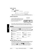
Страница 51: ...oportionnelle niveau haut 20 mA niveau haut 4 mA niveau bas 4 mA niveau bas 20 mA Presser 4 Presser 4 à nouveau Etalonnage 4 mA Nouvelle référence 4 mA Recommencer étalonnage incomplet Le Probe étant correctement installé ou orienté vers un mur à une distance de 0 25 à 5 m effectuer sa mise sous tension L afficheur du Probe indique initialement mode programmation alphanumérique unités perte d écho...

Страница 52: ...ériau dans la cuve ou une cible n est pas disponible Cette méthode peut également être utilisée pour ajuster les valeurs programmées via la méthode Référence se référer à la page 7 Pour modifier les valeurs d étalonnage programmées visualiser c 4 ou c 20 Pour augmenter la valeur d étalonnage presser 20 Pour diminuer la valeur presser 4 Lorsque la valeur souhaitée est obtenue cesser de presser les ...

Страница 53: ...pressée pendant le réglage de la valeur et relâcher lorsque la valeur souhaitée apparaît Presser 4 pour décrementer jusqu à 0 45 m par exemple Nouvelle valeur 3 sec Zone morte Valeur programmée de la zone morte exemple 0 25 m Presser 20 pour augmenter la zone morte exemple 0 36 m Note Pour un étalonnage plus rapide maintenir la touche pressée pendant le réglage de la zone morte et relâcher une foi...

Страница 54: ...i Le Probe ne peut pas s adapter aux vitesses de variation de niveau modifier le réglage de 1 à 2 Si cette condition persiste sélectionner l option de réglage 3 Eviter de sélectionner une option qui soit trop rapide pour l application en cours Discrimination d écho Permet de discriminer entre les échos produits par les pales d agitateur et la surface du matériau Filtre Permet de discriminer entre ...

Страница 55: ...écurité défaut visualiser FSt La valeur de la temporisation peut être augmentée avec la touche 20 et diminuée en pressant 4 Cesser de presser la touche dès que la valeur souhaitée est affichée L affichage revient automatiquement au mode Run 6 secondes Unités La lecture de la mesure peut être réglée pour un affichage en 1 mètres m réglage en usine 2 pieds ft L unité de mesure sélectionnée peut égal...

Страница 56: ...afraîchir la mesure Les causes probables sont Matériau ou cible en contact avec la face émettrice du capteur Le Probe est trop proche du point de remplissage Le Probe n est pas perpendiculaire à la surface liquide Variation du niveau trop rapide Mesure en dehors de la plage Présence de mousse à la surface du liquide Vibrations importantes de la structure de montage Niveau produit dans la zone mort...

Страница 57: ...sur la plage de température de fonctionnement Afficheur cristaux liquides 3 chiffres hauteur 9 mm 0 35 pour lecture en mètres de la distance capteur produit mesuré graphique multi segments pour les états de fonctionnement Sortie analogique plage 4 à 20 mA étendue proportionnelle ou inversement proportionnelle précision 0 25 de la pleine échelle résolution 3 mm 0 25 charge 600 ohms maximum sous ali...

Страница 58: ...TICK Rapport de performance CEM disponible sur demande Sécurité intrinsèque CSA FM sécurité intrinsèque pour zones dangereuses Class I II Div 1 GR A B C D E F G ATEX II 1 G BAS99ATEX1300 INMETRO DNV 12 0071X Ex ia IIC T4 Ga IP65 40 C Ta 60 C DNV OCP 0017 ABNT NBR IEC 60079 0 2008 e ABNT NBR IEC 60079 11 2009 ...

Страница 59: ...IQ300IX fm Page 5 Tuesday October 2 2001 1 43 PM ...

Страница 60: ...ous weighing www siemens com level For more information www siemens com processautomation Siemens AG Industry Sector 1954 Technology Drive P O Box 4225 Peterborough ON Canada K9J 7B1 Subject to change without prior notice A5E32243983 Rev AA email techpubs smpi siemens com Siemens AG 2013 ...

Отзывы: