background image

187/238 

Building Technologies 

Modular Heating Controller RMH760B 

CE1P3133en 

HVAC Products 

12 Function block miscellaneous 

05.02.2007 

12 

Function block miscellaneous 

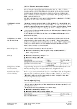
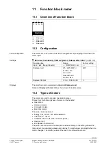
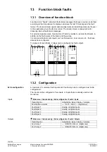
12.1  Overview of function block  


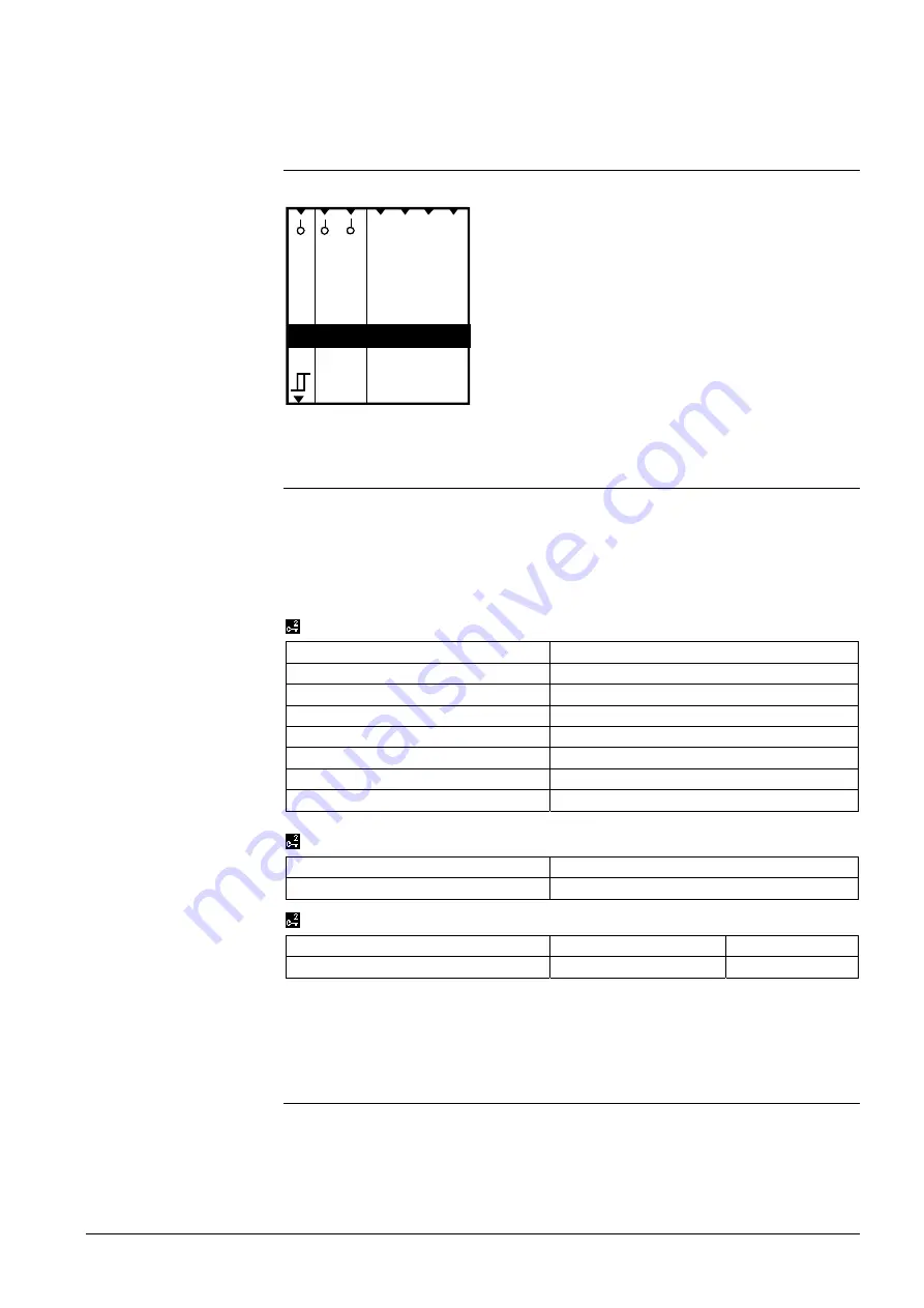
a

x x x

x

a

Q

a

Di

sp

la

y 1

Di

sp

la

y 2

 Di

sp

la

y 3

Di

sp

la

y 4

Wi

nd

So

la

r

Ou

ts

id

e

Miscellaneous


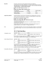
12.2 Configuration 


Function block “Miscellaneous“ is always available. To activate the function block, no 
special basic configuration is required. 

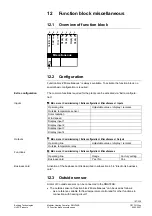
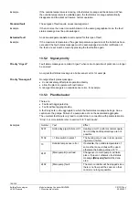
The common functions required for the plants can be activated via “Extra configura-
tion”. 

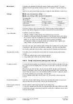
  Main menu > Commissioning > Extra configuration > Miscellaneous > Inputs 

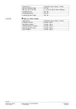
Operating line  

Adjustable values / display / remarks


Outside temperature sensor 


Solar radiation 


Wind speed 


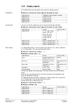
Display input 1 


Display input 2 


Display input 3 


Display input 4 


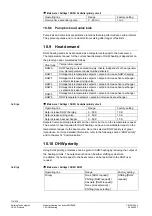
  Main menu > Commissioning > Extra configuration > Miscellaneous > Outputs 

Operating line  

Adjustable values / display / remarks


Outside temperature relay 


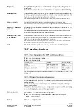
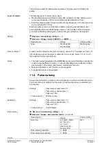
  Main menu > Commissioning > Extra configuration > Miscellaneous 

Operating line 

Range 

Factory setting 

Business card 

Yes / No 

Yes 

 
Activation of the business card is described in subsection 4.5.4 “Electronic business 
card”.  

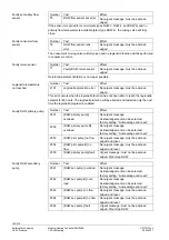
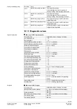
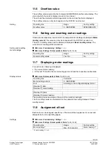
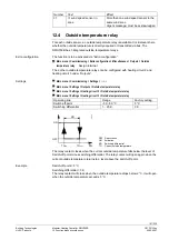
12.3 Outside 

sensor 


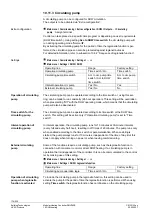
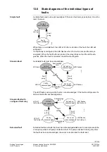
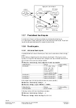
A total of 3 outside sensors can be connected to the RMH760B:  

  The outside sensor at function block “Miscellaneous“ can be used as follows: 


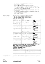
As a reference variable for flow temperature control and for other functions in 
connection with heating circuit 1 

Extra configuration  

Inputs 

Outputs 

Functions 

Business card 

Содержание Synco 700

Страница 1: ... 1 0 Controller series B CE1P3133en 05 02 2007 Building Technologies HVAC Products Synco 700 Modular Heating Controller RMH760B including extension modules RMZ782B RMZ783B RMZ787 and RMZ789 Basic Documentation ...

Страница 2: ...ler RMH760B CE1P3133en HVAC Products 05 02 2007 Siemens Switzerland Ltd Building Technologies Group HVAC Products Gubelstrasse 22 CH 6301 Zug Tel 41 41 724 24 24 Fax 41 41 724 35 22 www sbt siemens com 2007 Siemens Switzerland Ltd Subject to alteration ...

Страница 3: ... 19 3 2 Basic configuration 19 3 2 1 Selecting the plant type 19 3 2 2 Terminal assignment and properties of outputs 28 3 2 3 Short designations for basic module and extension modules 29 3 2 4 Use of the configuration diagrams 29 3 2 5 Extension modules 31 3 3 Extra configuration 33 3 3 1 General 33 3 3 2 Configuration of the universal inputs and outputs 34 3 4 Wiring test 36 3 5 Completing commis...

Страница 4: ...nputs for holidays and special days 49 5 2 6 Fault handling 50 5 3 Frost protection for the plant 51 5 4 Pump overrun and mixing valve overrun 52 5 5 Pump kick and valve kick 53 5 6 Heat demand and load control 53 5 6 1 Heat demand 53 5 6 2 Load control 54 5 7 Mixing valve control 56 5 7 1 Control 56 5 7 2 Setting aids 56 5 7 3 Control signal 59 5 8 Pump control and twin pumps 59 5 8 1 Changeover ...

Страница 5: ... 6 6 9 Boiler shutdown 81 6 6 10 Frost protection for the boiler 82 6 6 11 Maintained boiler return temperature 82 6 6 12 Protection against pressure shocks 84 6 7 Flue gas temperature supervision 85 6 8 Flue gas measuring mode 86 6 9 Boiler faults 86 6 10 Burner hours run counter and burner start counter 88 6 11 Fault handling 89 6 12 Text for boiler designation 90 6 13 Diagnostic choices 90 7 He...

Страница 6: ...des in the heating circuit 113 9 3 1 Room operating modes 113 9 3 2 User request in the room 115 9 3 3 Room operating mode contact 115 9 3 4 Timer function 116 9 3 5 Room operating mode outputs 116 9 3 6 Plant operation 118 9 3 7 Control priorities in the heating circuit 118 9 4 Room temperature setpoints 120 9 4 1 Settings 120 9 4 2 Raising the Economy setpoint 121 9 4 3 Room temperature setpoint...

Страница 7: ...12 Diagnostic choices 146 10 DHW heating 147 10 1 Overview of function block 147 10 2 Configuration 148 10 2 1 General 148 10 2 2 DHW plant types 149 10 2 3 3 position or modulating mixing valve 150 10 2 4 Pump control 151 10 3 Operating modes and setpoints 151 10 3 1 DHW operating modes 151 10 3 2 User request via digital inputs 152 10 3 3 Plant operation 153 10 3 4 Control priorities in DHW heat...

Страница 8: ...unctions 175 10 11 1 Text designation for DHW and time switches 175 10 11 2 Primary flow temperature sensor 175 10 11 3 Circulating pump 176 10 11 4 Electric immersion heater 177 10 11 5 System pump 177 10 11 6 Consumer control 178 10 12 Fault handling 179 10 13 Diagnostic values 181 11 Function block meter 183 11 1 Overview of function block 183 11 2 Configuration 183 11 3 Types of meters 183 11 ...

Страница 9: ...8 13 8 2 Analog fault input with limit value supervision 199 13 9 Communication 200 13 10 Fault relay 201 13 11 Fault display 202 13 12 Deleting all fault status messages 202 13 13 Diagnostic choices 202 14 Communication 204 14 1 Basic settings 204 14 2 Calendar data holidays and special days 205 14 3 Room data 206 14 3 1 Communication variants 206 14 3 2 Settings on the RMH760B 209 14 3 3 Setting...

Страница 10: ...0B CE1P3133en HVAC Products Contents 05 02 2007 16 1 4 Examples 221 16 2 Editable text 230 16 2 1 Heating circuits 230 16 2 2 DHW 230 16 2 3 Primary controller 230 16 2 4 Main controller 230 16 2 5 Boiler 230 16 2 6 Faults 231 16 2 7 Meters 231 16 2 8 Device 231 ...

Страница 11: ...roller RMH760B Extension modules Heating circuit module RMZ782B DHW module RMZ783B Universal module RMZ787 Universal module RMZ789 Module connector For detached extension modules RMZ780 Operator units Operator unit plug in type RMZ790 Operator unit detached RMZ791 Konnex bus operator unit RMZ792 Service unit Service tool OCI700 1 RMH760B RMZ782B RMZ783B RMZ787 RMZ789 RMZ780 RMZ790 RMZ791 RMZ792 ...

Страница 12: ...ent LG Ni 1000 N1713 and N1721 N1846 QAC22 with a sensing element LG Ni 1000 N1811 Outside sensors QAC32 with a sensing element NTC 575 N1811 Solar intensity sensor QLS60 N1943 QAA25 N1721 QAA27 N1721 Room units QAW740 N1633 BSG21 1 N1981 BSG21 5 N1991 Passive setpoint adjusters QAA25 QAA27 N1721 Actuating devices All types of electromotoric and electrohydraulic actuators operating on AC 24 V for ...

Страница 13: ...vice tool OCI700 1 N5655 Installation Instructions for RMH760B and RMK770 G3133 Mounting Instructions for extension modules RMZ78 M3110 Mounting Instructions for detached operator unit RMZ791 M3112 Mounting Instructions for module connector RMZ780 M3138 Operating Instructions for heating controller RMH760B 1 de fr it es B3133x1 Operating Instructions for heating controller RMH760B 2 en de fr nl B3...

Страница 14: ...has been drawn to potential risks When wiring the system the AC 23 0V section must be strictly separated from the AC 24 V safety extra low voltage SELV section in order to ensure protection against electric shock For storage and transport the limits given in the relevant Data Sheets must always be observed If in doubt contact your supplier or SBT HVAC Products Synco 700 products are maintenance fr...

Страница 15: ... status message ready for acknowledgement LED lit Fault status message still present but not yet reset LED off No fault status message present Press button Acknowledgement of fault or reset 3 Button Prog for assigning the device address in Konnex system mode tool re quired 4 LED Prog for indicating programming LED lit LED remains lit until addressing is completed 5 LED Run for monitoring power sup...

Страница 16: ... Detached operator unit RMZ791 1 Display 2 INFO button Function 1 Display of key plant data Function 2 Display of information about the individual datapoints on the cur rent menu 3 OK select and press knob Turn Selection of operating line and adjustment of value Press Confirmation of operating line or setting 4 ESC button Going back to the previous menu 5 Fault button with LED LED Fault Press Ackn...

Страница 17: ...ting level is structured like a menu It provides for reading and adjustment of datapoints Using the INFO button explanations relating to the menus with the individual data points can be displayed The information is displayed as long as the button is kept depressed Switching from the info level to the setting level 1 Select the start page by pressing the ESC button 2 Press the OK knob to change to ...

Страница 18: ...pending on the access level On a higher access level it is always possible to also view all menu items and datapoints of the lower access levels There is only one menu the password level shows the entire menu After a time out 30 minutes with no action on the controller the controller switches to the user level unless the controller uses the Commissioning menu Switching from the current access leve...

Страница 19: ... they are enclosed with the controller 3 2 Basic configuration A plant is always configured on the password levels and district heat parame ters Main menu Commissioning Basic configuration Operating line Adjustable values display remarks Plant type Basic type H H0 1 H6 7 Position 1 RMZ782 RMZ783 RMZ787 RMZ789 Position 2 RMZ782 RMZ783 RMZ787 RMZ789 Position 3 RMZ782 RMZ783 RMZ787 RMZ789 Position 4 ...

Страница 20: ...nly 2 Control of one heating circuit 3 Heat source 3 DHW heating and control of one heating circuit 4 Heat source with maintained boiler return temperature 4 Control of 2 heating circuits 5 Consumer connected to district heating with storage tank charging and control of mixing valve as a preselected DHW type 5 DHW heating and control of 2 heating circuits 6 Consumer connected to district heating w...

Страница 21: ...X2 H0 2 H0 3 A3 N1 DHW circuit DHW 2 Heating circuit N1 3133S03 A3 N X1 N Q3 N Q1 Q2 N X2 A3 X2 A3 Q1 Q2 A3 Q5 A3 X1 H0 3 H0 4 N1 A2 Heating circuit Heating circuit A2 3133S04 N1 N X1 N Q3 N Q1 Q2 N X2 A2 X1 A2 Q3 A2 Q1 Q2 H0 4 H0 5 A3 N1 A2 DHW circuit DHW 2 Heating circuit Heating circuit A2 N1 3133S05 A3 A3 X2 A3 Q1 Q2 A3 Q5 A3 X1 H0 5 N X1 N Q3 N Q1 Q2 N X2 A2 X1 A2 Q3 A2 Q1 Q2 H0 6 N1 A2 1 A2...

Страница 22: ...circuit control with mixing valve and circulating pump connected to the secondary circuit of the main flow A2 3133S11 N1 N X1 H1 2 A2 X1 A2 Q3 A2 Q1 Q2 N X2 N X3 N Q1 Q2 H1 3 N1 A3 A2 Main controller DHW circuit DHW 4 Heating circuit A2 A3 3133S12 N1 H1 3 A3 Q1 Q2 A3 Q5 A3 X2 A3 X4 A2 X1 A2 Q3 A2 Q1 Q2 N X2 N X1 N X3 N Q1 Q2 A3 Q3 H1 4 N1 A2 1 A2 2 Main controller Heating circuit Heating circuit A...

Страница 23: ... circuit A2 A3 3133S19 N1 N X1 N Q3 N Q1 Q2 H2 3 A3 X2 A3 Q1 Q2 A3 Q5 A3 X1 A2 X1 A2 Q3 A2 Q1 Q2 N X2 H2 4 N1 A2 1 A2 2 Primary controller Heating circuit Heating circuit A2 2 A2 1 3133S20 N1 N X1 N Q3 N Q1 Q2 H2 4 A2 X1 A2 Q3 A2 Q1 Q2 N X2 A2 X1 A2 Q3 A2 Q1 Q2 H2 5 N1 A3 A2 1 A2 2 Primary controller DHW circuit DHW 2 Heating circuit Heating circuit A2 1 A3 A2 2 3133S21 N1 N X1 N Q3 N Q1 Q2 H2 5 A...

Страница 24: ... A2 X1 A2 Q3 A2 Q1 Q2 N X1 N Q3 N X3 N Q5 H3 5 N1 A3 A2 1 A2 2 Boiler temperature control DHW circuit DHW 2 Heating circuit Heating circuit H3 5 A2 1 A3 A2 2 N1 3133S28 A2 X1 A2 Q3 A2 Q1 Q2 N X2 A2 X1 A2 Q3 A2 Q1 Q2 A3 X2 A3 Q1 Q2 A3 Q5 A3 X1 N X1 N Q3 N X3 N Q5 H4 0 N1 Boiler temperature control with 1 stage burner and boiler pump controlled mixing valve for main tained boiler return temperature ...

Страница 25: ... H4 5 A3 N1 3133S35 A3 X2 A3 Q1 Q2 A3 Q5 A3 X1 N X2 N X1 N Q3 N X3 N Q5 N Q1 Q2 A2 2 A2 1 A2 X1 A2 Q3 A2 Q1 Q2 A2 X1 A2 Q3 A2 Q1 Q2 H5 2 N1 Weather compensated heating circuit control via heat exchanger connected to uncontrolled main flow with 2 port valve in the primary return 3133S37 N1 N X1 N Q3 N Q1 Q2 N X3 H5 2 N X2 H5 3 A3 N1 DHW circuit with storage tank charging via heat exchanger connecte...

Страница 26: ...ing circuit Heating circuit Heating circuit A2 1 N1 A2 2 3133S47 N Y1 N Q5 N X5 H6 7 N X1 N Q3 N Q1 Q2 N X3 A2 X1 A2 Q3 A2 Q1 Q2 A2 X3 A2 X1 A2 Q3 A2 Q1 Q2 A2 X3 N X2 N Connection terminals of heating controller N1 A2 Connection terminals of heating circuit module RMZ782B A2 1 Connection terminals of the first heating circuit module RMZ782B if 2 heating circuit modules are used A2 2 Connection ter...

Страница 27: ...irculating pump DhwPrPu DHW primary pump MnPu Main controller pump PrCtrPu Primary controller pump system pump PUHCx Heating circuit pump x x 1 3 TBo Boiler temperature TFlDhwCons DHW flow temperature consumer TFlSecDhw DHW flow temperature secondary side TFlHCx Flow temperature heating circuit x x 1 3 TFlMnPrCtr Flow temperature main controller TFlPrCtr Flow temperature primary controller TFlPrDh...

Страница 28: ...ition control of a mixing valve or modulating burner with on off signal appropriate radio interference suppression measures must be taken If the mixing valve does not already incorporate such an RC unit appropriate devices must be provided either on the controller side or externally Q12 Q11 Y1 N Y2 AC 24 230 V 3133A04 N1 N2 Q14 Q23 Q24 Connection of suppression units When terminals N1 and N2 or N3...

Страница 29: ...1 First of 2 extension modules RMZ782B A2 2 Second of 2 extension modules RMZ782B A3 Extension module RMZ783B A7 Extension module RMZ787 A9 Extension module RMZ789 A9 1 First extension module RMZ789 A9 2 Second extension module RMZ789 These short designations also appear on the operator unit 3 2 4 Use of the configuration diagrams Use of the configuration diagrams is explained on the basis of plan...

Страница 30: ...edback Time switch Holiday Special day 2 Pos output To do a configuration From capital letter to capital letter From small letter to small letter Capital letter Physical in or output Small letter internal signal Or selection And selection Heat requis Frost Flow R eturn close open Main pump Display 1 Display 2 Display 3 Display 4 Wind Solar Outside Legionella function relay Primary Flow Return Flow...

Страница 31: ...t be reconfigured Type of module Input variable Terminal Designation in diagram RMZ783B Primary flow sensor X1 A3 X1 Storage tank sensor at the top X2 A3 X2 RMZ782B 1 Flow sensor X1 A2 X1 RMZ782B 2 Flow sensor X1 A2 X1 Type of module Output variable Terminal Designation in diagram 3 position primary mixing valve Q1 and Q2 A3 Q1 Q2 RMZ783B Primary pump Q5 A3 Q5 3 position mixing valve Q1 and Q2 A2 ...

Страница 32: ...at a free position of the controller The controller can accept a maximum of 4 extension modules Of module types RMZ783B DHW and RMZ787 universal a maximum of one module can be used of heating circuit module type RMZ782B and universal module type RMZ789 a maximum of 2 of each 3 2 6 Basic configuration Configuration of the controller is always started by defining the plant type Based on the selected...

Страница 33: ...re of advantage to have all pending faults displayed Number Text Effect 7101 Fault extension module Urgent message must be acknowledged In the event of fault the LEDs on the extension modules flash If everything works correctly the LEDs are lit 3 3 Extra configuration 3 3 1 General By configuring additional inputs and outputs adaptations to the hydraulic circuit can be made and extra functions and...

Страница 34: ...minals and the number of plant elements pumps and actuators or positioning outputs Plant element Maximum number Pumps 6 Positioning outputs 6 Following applies A twin pump is regarded as one pump A positioning output is used for an actuator or a modulating burner If both the modu lating output and the 3 position positioning output are configured the 2 are regarded as one positioning output 3 3 2 C...

Страница 35: ...ctive signal of DC 0 10 V 0 100 C Lower limit value 0 C Upper limit value 100 C With passive temperature sensors the measured value can be readjusted by 3 0 3 0 K to compensate for line resistance It is thus possible to make onsite calibrations with a reference instrument Main menu Commissioning Settings or Main menu Settings Inputs X Operating line Range Factory setting Correction 3 0 3 0 K 0 0 K...

Страница 36: ...is test after the configuration and the settings have been made The current states are indicated at the inputs The aggregates connected to the outputs pumps actuators etc or messages e g for conventional controllers can be switched on and off In the case of modulating outputs a signal can be delivered in the relevant value range The application is deactivated during the wiring test The outputs are...

Страница 37: ...ning Heating circuit 1 Heating circuit 2 Heating circuit 2 3 6 Data backup When commissioning is completed the entire commissioning data set configuration and all settings can be saved in the controller If any time later an unauthorized per son readjusts important values this function can be used to restore the correct con trolled state after commissioning Main menu Data backup Operating line Adju...

Страница 38: ...aving the password level On completion of commissioning select the user level access level for the plant opera tor Proceed as follows 1 After completing commissioning you reach the Main menu again 2 Press simultaneously the OK knob and the ESC button 3 The Access levels menu appears 4 Select the user level by turning the OK knob 5 Confirm the selection by pressing the OK knob 3 9 Marking an interv...

Страница 39: ... of the earliest changeover can be readjusted should the relevant regulations change The dates set for the change from wintertime to summertime and vice versa ensure that on the first Sunday after that date the time of day will change from 02 00 winter time to 03 00 summertime and from 03 00 summertime to 02 00 wintertime If both dates are set to coincide summer wintertime changeover will be inact...

Страница 40: ...ntr time System time Readjustment Slave Remote setting clock slave Yes The time of day on the controller can be readjusted which at the same time readjusts the system time The controller s time of day is continuously and automatically matched to the system time 3140Z06 Contr time System time Readjustment Master The time of day on the controller can be readjusted and at the same time readjusts the ...

Страница 41: ...nguage 4 Language 5 Language 6 RMH760B 1 German French Italian Spanish RMH760B 2 German English French Dutch RMH760B 3 Swedish Finnish Norwegian Danish RMH760B 4 Polish Czech Hungarian Russian Slovakian Bulgarian RMH760B 5 Greek Romanian Slovenish Serbian Croatian Turkish Main menu Commissioning Settings or Main menu Settings Device Operating line Range Factory setting Language English Available w...

Страница 42: ...tered The change of text designation for the boiler only affects the menu headings indicated but not the fault texts and not the text of operating lines 4 5 3 Texts for the fault inputs The texts for the fault inputs are locally displayed and also transmitted via bus In addition to the predefined fault inputs there are 4 universal fault inputs 3 digital and freely usable boiler related fault input...

Страница 43: ...ts Operating line Range Factory setting Business card line 1 Max 20 characters Business card line 2 Max 20 characters Business card line 3 Max 20 characters Business card line 4 Max 20 characters 4 5 5 Resetting text entries The following datapoints cannot be reset Device name File name Business card lines 1 4 All other texts such as menu text fault text etc entered by the user can be reset on the...
Страница 44: ...ler The following settings must be made depending on the required operating mode Required time switch operation Operating line Setting Geographical zone apartm Autonomous Time switch slave apartm Geographical zone apartm 1 126 Master Time switch slave apartm Geographical zone apartm Any Slave Time switch slave apartm 1 126 The following combinations are possible Effect Description Diagram Autonomo...

Страница 45: ...r space heating a specific 24 hour program can be selected for each day Main menu Heating circuit 1 or 2 or 3 Time switch 1 or 2 or 3 Operating line Range Factory setting Monday Comfort Precomfort Economy From 06 00 Com fort From 22 00 Economy up to Sunday Comfort Precomfort Economy From 06 00 Com fort From 22 00 Economy Special day Comfort Precomfort Economy From 06 00 Com fort From 22 00 Economy...

Страница 46: ...another entry is made The operating mode of the previous day is shown in the form of a broken line Cmf PreCmf Eco 1 3131D25 Monday Tuesday Wednesday If no entry is made for a specific day the operating mode of the previous day will be adopted for the whole day and shown as a broken line The special day ends with the same operating mode with which it was started The day following the special day ad...

Страница 47: ...ller will operate in Comfort mode In that case fault status message System time switch failure 1 or 2 or 3 will be delivered 5 2 Holidays and special days Each heating circuit and DHW heating use their own holidays special day program Weekdays deviating from the normal 7 day program can be entered by the plant opera tor as holidays or special days using the Holidays special days menu Entry is desc...

Страница 48: ...pecial day communication refer to chapter 5 2 2 Holidays 5 2 2 Holidays Holidays are periods of time during which the building is not occupied whose start and duration are known in advance Examples Works holidays in commercially used spaces and buildings School holidays in school buildings Public holidays The operating mode to be used during the holiday period can be set separately for each heatin...

Страница 49: ...ecial day zone 5 2 4 Calendar entry A maximum of 16 entries can be made The entries are sorted in chronological order Every entry must include Date year and start time Date and end time Reason for entry holidays or special day Main menu Holidays special days Operating line Range Factory setting Entry 1 Entry 16 Start End Reason Holidays Annually recurring holidays or special days can be entered by...

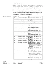
Страница 50: ...try in the calendar If other controllers are also configured as slaves in the same holidays special day zone the digital inputs will act on these controllers also 5 2 6 Fault handling Only one master may be set per holidays special day zone If there is more than one master in a zone fault status message 1 hol sp day prgm HC 1 or HC 2 or HC 3 or DHW will be delivered The fault is identified by the ...

Страница 51: ...side temperature This takes place independent of heat requests Prerequisite is however that Frost protection for the plant has been activated for the relevant pump Main menu Commissioning Settings or Main menu Settings Heating circuit 1 or 2 or 3 Limitations Operating line Range Factory setting Frost protection for the plant Off On On Main menu Settings DHW Limitations Operating line Range Factory...

Страница 52: ... period of time an overrun time is enforced on the heat consumers that were switched off within the last minute During that overrun time the pumps and mixing valves continue to operate the pumps continue to run and the mixing valves maintain the old setpoint The duration of the overrun time is dependent on the type of heat source used and can therefore be set on the boiler Main menu Commissioning ...

Страница 53: ...onnected to the RMH760B If a plant uses several RMH760B the setting must be made on each of them With the kick day and kick time settings it is to be noted that these settings are also used for automatic changeover of twin pumps for more detailed information refer to section 5 8 Pump control and twin pumps The kick time for pumps and actuators need not be set it is fixed at 30 seconds If several p...

Страница 54: ...rol Load control enables heat generation to reduce the amount of heat drawn by the heat consumers load reduction via locking signals or to increase it load increase via forced signals In the case of load control via locking signals a differentiation is made between critical and uncritical locking signals In the case of forced signals also a distinction is made between critical and uncritical signa...

Страница 55: ...Settings Heating circuit 1 or 2 or 3 Mixing circuit controller Operating line Range Factory setting Response uncrit locking signals Yes No Yes Locking signal gain 0 200 100 Main menu Commissioning Settings or Main menu Settings DHW Controller primary circuit Main menu Settings Main controller Mixing circuit controller Main menu Settings Primary controller Mixing circuit controller Operating line R...

Страница 56: ... Main menu Settings DHW Controller maint sec temp Main menu Settings DHW Controller consumers Main menu Settings Primary controller Mixing circuit controller Main menu Settings Main controller Mixing circuit controller Main menu Settings Boiler Return control Operating line Range Factory setting Actuator run time 1 600 s P band Xp 1 100 K Integral action time Tn 0 600 s Depending on various settin...

Страница 57: ...f the mixing valve and the minimum return tempera ture for example The value of Ksmax may have to be increased to give consideration to a nonlinear valve characteristic TVmax 80 C and TRmin 20 C Ksmax 60 K P band Xp 2 Tu Tg Δx Δy 100 2 Tu Tg Ksmax Integral action time Tn 3 Tu Change of valve position Δy 40 Change of flow temperature Δx 18 K Tu 6 s Tg 18 s P band Xp 2 6 s 18 s 18 K 40 100 30 K Inte...

Страница 58: ...uators the setting is to be increased since otherwise the actuator will not optimally operate in the range between 0 and 100 stroke also refer to synchronization pulse in subsection 5 7 3 It is important to also set the actuator running time with DC 0 10 V actuators Only this ensures correct operation of the control system The P band Xp is given in K Kelvin If after a setpoint step the control dev...

Страница 59: ... becomes more stable 5 7 3 Control signal Since the control algorithm uses a stroke model which does not provide control beyond 0 and 100 respectively the use of electrothermal actuators is no longer possible as this was the case with the RVL47 controllers For 3 position control the actuator s current position is acquired by a stroke model As soon as the stroke model reaches 0 or 100 respectively ...

Страница 60: ... display remarks pump overload Assign terminal pump B overload Assign terminal Flow signal pump Assign terminal If a twin pump was configured the relevant function block will show menu item Twin pump Main menu Commissioning Settings or Main menu Settings Heating circuit 1 or 2 or 3 Twin pump Main menu Settings DHW Primary twin pump or Secondary twin pump or Circulating twin pump Main menu Settings...

Страница 61: ...terruption The change from pump A to pump B takes place instantly 3131D42 A B The change from pump A to pump B is made with temporal overlapping e g to ensure a low noise level during changeover The pump to be deactivated overruns for the adjusted period of time 3131D43 A B The change from pump A to pump B is made after a certain pause e g to prevent surge voltages or excessive water pressures 313...

Страница 62: ...d the acknowledgement and reset behavior can be parameter ized In the case of twin pumps the fault behavior of the respective function block becomes active only should both pumps fail Flow supervision only becomes active 60 seconds after the pump is switched on Number Text Description 2526 Heat circuit 1 pump over load Heating circuit pump of heating circuit 1 overloaded 2527 Heat circuit 1 pump B...

Страница 63: ...d d d 3133W11 F lue g as Release F lue g as m ode B urn er Boiler Return B urn er Shutoff valve Boilerp Bypassp Water shortage 1 Overpressure 2 Underpressure 3 Pump funct Boiler Modulating Stage close open Setpoint comp close open MBRT InFgMsm Error BoPuEr ErBu BuFb Er2 PMaxMon Er3 PMinMon Er1 WloLeDet ShOffVlvFb ShOffVlvFb BuFb BoPuEr_B BoPuErFlow BoSetpt VlvShOff BoPu BoPu_B VlvRtMx BuSt1 BuSt2 ...

Страница 64: ...temperature VlvShOff Shutoff valve VlvShOffFb Checkback signal shutoff valve 6 2 Configuration The function block is activated in the factory for plant types H3 x and H4 x Always preconfigured is a boiler with a 1 stage burner boiler pump boiler temperature and return temperature sensor For plant types H4 x a mixing valve with 3 position actuator for the maintained boiler return temperature is als...

Страница 65: ... limitation of the boiler temperature For plant types with boiler the return temperature sensor will always be configured too For plant types using maintained boiler return temperature control via the mixing valve this sensor is mandatory In all other cases the return temperature sensor can be used for maintained boiler return temperature via the bypass pump maintained boiler return temperature wi...

Страница 66: ...twin pumps Input for monitoring boiler pump flow 6 2 1 Burner types Selection of a plant type with boiler means that a 1 stage burner will be preselected Using Extra configuration other boiler types can be selected by configuring additional outputs 1 stage burner factory setting 2 stage burner Modulating burner Setpoint compensation First burner stage or basic stage of a modulating burner Second b...

Страница 67: ...iler return temperature with 3 position mixing valve is already configured Configuration of a terminal pair for a 3 position mixing valve is required The terminals available for selection are the free terminal pairs Q1 Q2 Q3 Q4 for the on and the off signal For that purpose the special terminal pairs with RC radio interference suppres sion must be used For more detailed information refer to subsec...

Страница 68: ...f valve is configured and there is no such signal on completion of the adjusted switch on delay time a fault status message will be delivered This fault will lead to a boiler fault For more detailed information refer to section 6 9 Boiler faults Main menu Commissioning Settings or Main menu Settings Boiler Fault settings Checkb sign shutoff valve Operating line Range Factory setting Signal delay s...

Страница 69: ...tion In operating mode Release DHW only heat requests from DHW digital input or via Konnex bus will be taken into consideration If Off is preselected the internal frost protection function remains active Heat re quests from an external consumer resulting from frost protection will also be consid ered This setting can be used to preselect a minimum request for the boiler controller which means that...

Страница 70: ...tting Frost prot release input off Off On On The boiler can also be locked depending on the outside temperature The boiler will be locked when the attenuated outside temperature exceeds the selected limit value The boiler will be released again when the composite outside temperature drops 1 K below the limit value Main menu Commissioning Settings or Main menu Settings Boiler Operation settings Ope...

Страница 71: ...sed and the modulating burner runs to the modulation level according to the setting made The burner will be switched off when the maximum boiler tempera ture limit value is exceeded 6 5 1 2 position control with 1 stage burner Adjustable variables for 2 position control with a 1 stage burner Boiler s switching differential Minimum burner running time Main menu Commissioning Settings or Main menu S...

Страница 72: ...imum burner running time SDBo Boiler s switching differential t Time TBo Boiler temperature TBoSetpt Boiler temperature setpoint 6 5 2 2 position control with 2 stage burner Main menu Commissioning Settings or Main menu Settings Boiler Burner Operating line Range Factory setting Release limit stage 2 0 500 K m 50 K m Reset limit stage 2 0 500 K m 10 K m Locking time stage 2 0 60 min 10 min 6 5 3 C...

Страница 73: ... on the controller will build up the release integral If the boiler temperature lies above the switch on point the controller will reduce the release inte gral Through the generation of the temperature time integral it is not only the period of time that is considered but also the extent of undershoot This means that when the undershoot is significant the release after the integral criterion will ...

Страница 74: ...er stage 2 will be locked earlier When the reset integral area b in the diagram reaches the set value of the reset integral of stage 2 point in time treset stage 2 will be locked and the basic stage switched off 1 0 INT max RlsBuSt2 1 0 BuSt2 t RlsINT 3133D15 0 1 0 t t t t BuSt1 max TBoSrtpt 1 2SDBo TBo RstINT TBoSetpt 1 2SDBo RstINT BuSt1 Burner stage 1 SD Switching differential BuSt2 Burner stag...

Страница 75: ...burners separate unit in the case of large heavy oil burners P Oil pump coupled to fan motor Q Flame detector SA Electromotoric air damper actuator Z Ignition transformer The functioning with regard to activation and deactivation of the basic stage corre sponds to that of 2 stage burner operation Release of modulation is analogous to the release of the second stage The parameters used for the rele...

Страница 76: ...ral action time no more positioning pulses will be delivered If the boiler temperature does not stay long enough in the neutral zone or outside of it positioning pulses will drive the actuator toward the fully open or fully closed position Maximum limitation of the boiler temperature and minimum burner running time are handled analogously to 2 stage burner operation Control of the air damper must ...

Страница 77: ... control system with the preset control parameters the following procedure is recommended After the controller has reached and held the setpoint for a certain period of time change the setpoint by 5 to 10 either up or down When making this test it is of advantage to have the plant operating in the lower load range where usually control is more difficult In principle control must be stable but it c...

Страница 78: ...oiler Setp compensation boiler Operating line Range Factory setting Setpoint at 0 Volt 150 50 C 0 C Setpoint at 10 Volt 50 500 C 100 C Limit value 0 140 C 10 C Using setting parameters the DC 0 10 V output can be matched to the receiver s input In the case of setpoints below the limit value the output indicates DC 0 V 6 6 Protective boiler functions Main menu Commissioning Settings or Main menu Se...

Страница 79: ... calculated Maintenance of the minimum boiler temperature is dependent on the boiler shutdown setting see below When there is a heat request the minimum boiler temperature is always active If a minimum return temperature is required it must be ensured that the minimum boiler temperature will be set to a level which lies a few K above the minimum return tempera ture 6 6 3 Optimization of minimum bo...

Страница 80: ...f 60 seconds For more detailed information refer to section 5 4 Pump overrun and mixing valve overrun The overrun time also applies to boiler pumps and shutoff valves including mixing valves for the maintained boiler return temperature 6 6 5 Pump kick and valve kick The pump kick is a protective function which is performed periodically It prevents pumps and or valves from seizing after longer off ...

Страница 81: ...st protection for the plant the boiler temperature gradient must turn positive within 15 minutes Otherwise the locking signal will become invalid for at least 15 minutes Protective boiler startup becomes active after 15 minutes as soon as the boiler temperature gradient turns positive 6 6 9 Boiler shutdown Main menu Commissioning Settings or Main menu Settings Boiler Protective boiler startup Oper...

Страница 82: ...ly one boiler return sensor may be used since its measured value can generate a locking signal Locking signals may only have one single source 3133S71 BoPu TBo TRtBo If the boiler return temperature drops below the limit value a locking signal will be generated and delivered to all consumers These will then lower their setpoints or switch their pumps off e g the storage tank charging pump The type...

Страница 83: ...ere is no demand for heat Br ByP TiOverrunCnsm TBoR t min 10 20 30 60 50 40 30 TBoRmin SDByP TBo TBoRmin 0 1 t 0 1 t 3131D05 Br Burner ByP Bypass pump SDByP Switching differential of bypass pump t Time TBo Boiler temperature TBoR Boiler return temperature TBoRmin Minimum limit value of the boiler return temperature TiOverrunCnsm Consumer overrun time After the burner has been shut down pump overru...

Страница 84: ...ntrol Operating line Range Factory setting Actuator run time 1 600 s 120 s P band Xp 1 100 K 50 K Integral action time Tn 0 600 s 60 s If a minimum return temperature shall be ensured the minimum boiler temperature must be selected accordingly The minimum boiler temperature must be higher than the minimum return temperature In the case of plants with mixing valve for the maintained boiler return t...

Страница 85: ...ing value e g to 0 C whereupon the slave pointer will start at zero again The maximum value is filtered to suppress faults This means that the maximum flue gas temperature rises at a maximum rate of 1 K s If a flue gas temperature limit value is parameterized a fault status message will be delivered should the limit value be exceeded Main menu Commissioning Settings or Main menu Settings Boiler Fa...

Страница 86: ...n will automatically be ended after 30 minutes 6 9 Boiler faults If a boiler initiates lockout it will be shut down until the fault is rectified A boiler is considered faulty if one of the following faults occurred Burner fault Boiler pump fault Fault of shutoff valve no checkback signal Maximum permissible flue gas temperature exceeded if plant stop is required One of the 3 digital fault inputs i...

Страница 87: ...y setting Signal delay start 00 05 59 55 m s 02 00 m s Main menu Commissioning Settings or Main menu Settings Boiler Fault settings Fault burner Operating line Range Factory setting Fault acknowledgement None Acknowledge Acknowledge and reset Acknowledge Main menu Commissioning Settings or Main menu Settings Boiler Fault settings Checkback signal burner Operating line Range Factory setting Signal ...

Страница 88: ...in menu Settings Boiler Fault settings Flue temp supervision Operating line Range Factory setting Flue gas temperature limit value 8 400 C C Impact of fault No stop Stop No stop Fault priority Urgent Not urgent Nonurgent 6 10 Burner hours run counter and burner start counter For burner stage 1 or the burner s basic stage a checkback signal can be configured In addition to burner supervision this c...

Страница 89: ...tory setting Acknowledge Boiler stop 2311 Burner no checkback signal Urgent message must be acknowledged and reset Effect can be parameterized factory setting Stop Boiler stop Number Text Effect 2321 Boiler water shortage Priority effect and acknowledgement can be parameterized Factory setting Urgent Boiler stop must be acknowledged 2331 Boiler overpressure Priority effect and acknowledgement can ...

Страница 90: ...ting Boiler Max 20 characters Boiler If required specific text can be used to designate the boiler This text will then appear on the menu and on the info display 6 13 Diagnostic choices Main menu Boiler Inputs setpoints Operating line Adjustable values display remarks Release input Actual value boiler temperature Boiler temperature setpoint Actual value return temp Return temperature min Checkb si...

Страница 91: ...s display remarks Burner stage 1 Burner stage 2 Signal modulating burner Setpoint compensation Boiler pump Boiler pump B Shutoff valve Mix valve pos maint return temp Main menu Boiler Limitations Operating line Adjustable values display remarks Boiler temperature max Boiler temperature min Protective boiler startup Boiler return temperature min Burner run time min Outputs Limitations ...

Страница 92: ...rcuit External controllers via the Konnex bus As a continuous DC 0 10 V signal As a 2 position signal Heat requests can be delivered either via the main controller or the primary controller T 3133S90 T A B T Primary controller Main controller T T 3133S91 A B T Main controller Primary controller The internal heating circuit and the internal DHW circuit are connected to the main controller Connectio...

Страница 93: ...individual room radiator Heat request individual room air heating coil Heat request air handling Setpoint boost Heat demand transformers Heat demand transformers Setpoint boost Setpoint boost The connection via the main controller and primary controller is described in chapter 8 Main controller and primary controller 7 2 Heat demand outputs The main flow setpoint without giving consideration to li...

Страница 94: ...ert the position heat request signals in into heat demand signals with a flow temperature setpoint The following example of an air handling plant shows this T T T T RMH760B 3131B05 Room unit in reference room Central air handling DHW precontrol Chilled water precontrol Air supply area RMH760B RMU 0 100 3131B06 Precontrol heating Ventilation Precontrol refrigeration Heat demand transformer Refriger...

Страница 95: ...value request off 0 On value 5 3131D20 1 2 Outside temperature Flow temperature Curvepoint 1 Outside temp Max flow temp readjustment Curvepoint 1 Flow temp Curvepoint 2 Flow temp Curvepoint 2 Outside temp Adaptation of the flow temperature can be set as follows The rate of change of flow temperature readjustment can be set under Demand control Control action The kind of evaluation of the consumers...

Страница 96: ...2 2007 The On range and the Off range depend on the settings made 60 OFF 80 90 100 50 40 30 20 70 ON 3133D12 10 0 Limit value request on Limit value request off OFF 100 Setting range for limit value request On example with OFF 30 0 ON Setting range for limit value request Off example with ON 45 Setting the limit value request ...

Страница 97: ...Pu Mn SyPu B Mn SyPuEr Mn SyPuEr B Mn SyPuErFlow Primary controller use of mixing valve Main controller use of heat exchanger Mn SyPu Main system pump Mn SyPu B Main system pump B Mn SyPuEr Fault input main pump system pump Mn SyPuEr B Fault input main pump system pump B Mn SyPuErFlow Flow supervision main pump system pump TFl Flow temperature sensor TRt Return temperature sensor VlvMn PrCtr Mixin...

Страница 98: ...signal pump Heat request modulating Heating curve request 2 pos DHW request 2 pos Frost prot request 2 pos Heat requests from other devices can be accepted via bus In addition one analog and 3 digital inputs per function block are available for signaling heat requests 8 3 Controller types If only a pump or twin pump is configured the primary controller consists of system pump control A control loo...

Страница 99: ...tion about pump control and twin pumps refer to section 5 8 Pump control and twin pumps Main menu Commissioning Settings or Main menu Settings Main controller Fault settings Overload pump Operating line Range Factory setting Fault acknowledgement None Acknowledge Acknowledge and reset Acknowledge and reset Fault acknowledgement B None Acknowledge Acknowledge and reset Acknowledge and reset Main me...

Страница 100: ... request for the main controller can be preselected which means that maximum selection with the requests from the consumers will be main tained The primary controller s state is indicated On Off It is indicated why the current state is active 8 5 Heat demand and heat request MAX KNX KNX 3133Z11en Heat request heating circuits Heat request DHW Heat request primary controller Heat request heating cu...

Страница 101: ...ure setpoint for the primary controller The setpoint will be raised by the amount of the setpoint increase and forwarded to a heat source or another primary controller as Heat demand from precontrol 8 5 1 Heat request modulating Using a DC 0 10 V signal a heat request for the main controller or primary controller can be preselected The analog input can be matched to the DC 0 10 V signal source Mai...

Страница 102: ... perature and is determined with the same heating curve as that used for demand control For more detailed information about demand control refer to section 7 3 Heat demand transformer A signal received at input DHW request 2 pos is handled like a heat demand signal from DHW heating A constant setpoint can be preselected In addition priority of the resulting DHW request can be set For more detailed...

Страница 103: ... to preselect to what degree the primary controller shall respond to signals received from load control 8 6 2 Load control Load control signals from a heat source can have an impact on the primary controller A load reduction can be triggered by one of the following functions Protective boiler startup Minimum limitation of the boiler return temperature The primary controller does not respond to loc...

Страница 104: ...5 minutes 8 8 2 Limitations This setting is used to ensure maximum limitation of the flow temperature setpoint This setting is used to ensure minimum limitation of the flow temperature setpoint Minimum limitation is only active when there is a demand for heat The function can be deactivated by using setting This function is only available with primary controller type 1 The rate of increase of the ...

Страница 105: ...emperature Both the main controller and the primary controller offer maximum limitation of the return temperature depending on the active consumers The following types of limita tion are available Maximum limitation in space heating mode Maximum limitation in DHW heating mode Both have the following in common A return temperature sensor must be configured Limitation of the return temperature is on...

Страница 106: ...ely acting outside temperature Curvepoint 1 Maximum return temperature limit value active at low outside temperatures Curvepoint 2 Minimum return temperature limit value active at high outside temperatures Setting Effect Return temperature curvepoint 1 return temperature curvepoint 2 Constant limitation of the return tem perature Outside temperature is irrele vant Outside temperature curvepoint 1 ...

Страница 107: ...s Pulse limitation Main menu Settings Primary controller Limitations Pulse limitation Operating line Range Factory setting Meter input 1 4 Type of limitation Absolute Scaled Absolute Limit value 5 4000 pulses min 75 pulses min Integral action time Tn 0 255 min 60 min The meter input is an input of function block Meter which is used for limiting the number of pulses All inputs selected must be conf...

Страница 108: ...efer to section 5 5 Pump kick and valve kick 8 9 Text designation If required specific text can be assigned to the main controller or the primary controller This text will then appear on the menu and on the info display Main menu Commissioning Settings or Main menu Settings Main controller Operating line Range Factory setting Main controller Max 20 characters Main controller Main menu Commissionin...

Страница 109: ...ged and reset 2494 Main pump B no flow Nonurgent message must be acknowl edged and reset 2495 Main pump B fault Urgent message must not be acknowl edged Plant stop Number Text Effect 2501 System pump overload Nonurgent message Acknowledgement can be parameterized factory setting Acknowledge and reset 2502 System pump B over load Nonurgent message Acknowledgement can be parameterized factory settin...

Страница 110: ...in menu Main controller Outputs Main menu Primary controller Outputs Operating line Range Heat demand modulating C Heat demand relay Off On Main pump Off On Main pump B Off On System pump Off On System pump B Off On Mixing valve position 0 100 Only with main controller Only with primary controller Main menu Main controller Limitations Main menu Primary controller Limitations Operating line Range F...

Страница 111: ...O Outside sensor TR Room temperature sensor TRtHCtr Return temperature sensor 9 2 Configuration With the following plant types the heating circuits are activated per default Heating circuit 1 with plant types Hx 2 Hx 3 Hx 4 Hx 5 Hx 6 and Hx 7 Heating circuit 2 with plant types Hx 4 Hx 5 Hx 6 and Hx 7 Heating circuit 3 with plant types Hx 6 and Hx 7 Each heating circuit always has a mixing valve pu...

Страница 112: ...a configuration Miscellaneous Inputs The impact on the individual heating circuits can be parameterized For more detailed information refer to section 14 6 Weather data Main menu Commissioning Extra configuration Heating circuit 1 or 2 or 3 Inputs Operating line Adjustable values display remarks Outside sensor Flow sensor Room sensor Return sensor Return temperature limitation Room setpoint adjust...

Страница 113: ...a configuration Heating circuit 1 or 2 or 3 Outputs Mixing valve 3 pos Assign terminal 9 2 2 Pump control The heating circuit pump offers the same choices as all the other pumps An individ ual pump can also be monitored optionally a twin pump can be used as a heating circuit pump For that the relevant output must be configured For more detailed information refer to section 5 8 Pump control and twi...

Страница 114: ...t and the optimization functions will be influenced depending on the current room temperature setpoint Main menu Heating circuit 1 or 2 or 3 Room operating mode Operating line Range Factory setting Preselection Auto Comfort Precomfort Economy Protection Auto State Comfort Precomfort Economy Protection Cause Time switch 12 Holidays or 11 Special day or 11 Timer function or Konnex presence button Ro...

Страница 115: ...comfort and Economy The timer function is identical with the timer function triggered via a conventional but ton For this reason the setting used for the duration is also the same The mode of operation of this function is described in subsection 9 3 4 Timer function External switches or buttons for overriding the room operating mode can be connected to inputs Room operating mode and Timer function...

Страница 116: ...mode The input is to be activated via Extra configuration Main menu Commissioning Extra configuration Heating circuit 1 or 2 or 3 Inputs Timer function Assign terminal Main menu Commissioning Settings or Main menu Settings Heating circuit 1 or 2 or 3 Space heating Operating line Range Factory setting Timer function 0 720 min 60 min This setting does not apply to the QAW740 room unit in that case t...

Страница 117: ...R2 Precomfort relay control R1 R2 R1 R2 Economy relay control R1 R2 R1 R2 R2 Protection relay control R1 R2 R1 R2 R1 R2 The factory setting has been chosen such that the digital outputs can be connected directly to the digital inputs of the Synco 200 controller Since the Synco 200 controllers do not use the Precomfort mode an automatic change from Precomfort to Comfort mode will be made This setti...

Страница 118: ...ture protection overrun Plant operation selector No request Frost protection for the flow Frost protection for the plant Frost protection functions are ensured The heating circuit can be switched off for service purposes The mixing valve will close and the heating circuit pump will be deactivated on completion of pump overrun When preselecting Off the internal frost protection function remains act...

Страница 119: ...p mixing valve Timer button or mode button on QAW740 room unit Time switch Priority Name Explanation 1 Wiring test In the wiring test highest priority the plant compo nents can be directly controlled independent of all other settings The controller internal safety functions will be overridden 2 External master The plant operation selector has the second highest priority and can only be overridden ...

Страница 120: ...ll be activated in accordance with the current weekday The 24 hour program forwards the current room operating mode the next setpoint and the time up to the next switching point 9 4 Room temperature setpoints 9 4 1 Settings The setpoints for the 4 room operating modes can be preselected by the plant operator via operation The setting values limit each other Main menu Heating circuit 1 or 2 or 3 Ro...

Страница 121: ... TRSetptEco Δ TRSetptEco Δ TRSetptPreC Δ EndPt End point of increase 15 C in the graph SrtPt Starting point of increase 5 C in the graph TOeff Composite effectively acting outside temperature TRSetpt Room temperature setpoint TRSetptCmf Comfort setpoint TRSetptEco Economy setpoint TRSetptEco Δ Increased Economy setpoint TRSetptPreC Precomfort setpoint TRSetptPreC Δ Increased Precomfort setpoint Ma...

Страница 122: ...m setpoints From the difference between the fixed Comfort setpoint Heating and the adjustment made with the remote setpoint adjuster the current Comfort setpoint Cooling can be calculated Comfort setpoint Cooling remote setpoint minus Comfort setpoint Heating The RMH760B has no Comfort setpoint Cooling The impact on the Comfort setpoint Cooling as described above is only possible in connection wit...

Страница 123: ...tween the 2 setpoints will be maintained 9 4 4 Room temperature setpoint adjuster relative For room temperature setpoint readjustments in the Comfort and Precomfort modes a remote setpoint adjuster e g QAA27 with room temperature sensor can be configured The input is to be activated via Extra configuration Main menu Commissioning Extra configuration Heating circuit 1 or 2 or 3 Inputs Room setpoint...

Страница 124: ...Ofil Outside temperature filtered with the building time constant TOstrDmp Attenuated outside temperature τBldg Building time constant pWindow Proportion of windows in The composite outside temperature is made up of the actual outside temperature To and the outside temperature TOfil filtered with the building time constant τBldg The proportion of windows pWindow adjustable from 0 100 determines th...

Страница 125: ...heating curve is defined by 2 curvepoints 1 At the design temperature By the outside temperature TODef A By the flow temperature SetPTFlDef B 2 At the theoretical heating limit By the outside temperature TOHi C By the flow temperature SetPTFlHi D SetPTFlDe SetPTFlHi SetPTRN TFl TOeff TODe sHC TOHi B D A C 1 2 3131D24 The nonlinear heat transmission is considered by the radiator exponent nH The fol...

Страница 126: ... 9 K Hence the inflection point is at an outside temperature of 11 C nH 1 5 nH 1 0 30 K 100 9 K 30 10 5 0 5 10 15 20 25 60 50 40 30 20 10 0 TFl TO 3131D34 38 C 32 C 20 20 C The lift at the point of inflection is dependent on the flow temperature setpoint and the radiator exponent Rule of thumb for calculating the lift at the inflection point Lift Flow temperature setpoint at nH 1 20 C nH 1 Lift 32...

Страница 127: ...re setpoint only when room temperature influence is activated Connection of a room temperature sensor does not automatically activate the room influence An analog sensor can be used as a room temperature sensor Extra configuration or a room unit transmits the room temperature signal via bus In plants where the heating circuit operates in connection with a ventilation system as a room control combi...

Страница 128: ...etting Main menu Commissioning Settings or Main menu Commissioning Heating circuit 1 or 2 or 3 Optimizations influences Operating line Range Factory setting Impact of solar radiation 0 0 15 0 K 3131B23 TOeff Isun SpTFlDe SpTFlHi SpTRN TFl TOeff TODe TOHi sHc TFl sHc TFl Isun TRsnNom 1000 W m2 sHc 1 ΔTRsnNom Room temperature increase with 1000 W m2 Isun Filtered solar radiation sHc Heating curve sl...

Страница 129: ...e wind influence must always be matched to the location of the building The setting to be made is the room temperature drop ΔTrwdNorm resulting from a wind speed of 20 m s at a room temperature of 20 C and the design temperature A which corresponds to the lower curvepoint Based on this parameter and the current slightly attenuated wind speed the controller calculates the flow temperature readjustm...

Страница 130: ...endent of whether the operating mode was switched to Continuously Comfort or through the room operating mode contact Ex empted from this is the room control combination with an RMU7 ventilation controller here the heating limit is always active For operation in combination with the ventilation controller summer winter operation changeover is used as an overriding function When the attenuated outsi...

Страница 131: ...uction can be triggered by one of the following functions Protective boiler startup Limitation of the return temperature DHW heating with shifting priority DHW heating with absolute priority From the consumer s point of view a load increase can be effected in the form of pump and or mixing valve overrun In principle this means load maintenance 9 7 Optimization functions The opimization functions a...

Страница 132: ...e building time constant whereby the process is stopped as soon as the current room temperature setpoint is reached Main menu Commissioning Settings or Main menu Settings Heating circuit 1 or 2 or 3 Optimizations influences Operating line Range Factory setting Type of optimization With room model With room temp sensor With room model 9 7 2 Optimum start and stop control The purpose of optimum star...

Страница 133: ...en changing the room operating mode During the time quick setback is active the heating circuit pump is deactivated and the heating circuit s mixing valve fully closed The heating circuit remains off until the required room temperature is reached The Quick setback function can be deactivated on the service level Main menu Commissioning Settings or Main menu Settings Heating circuit 1 or 2 or 3 Opt...

Страница 134: ...fluences Operating line Range Factory setting Boost heating setp increase 0 20 K 5 K 9 8 Limit and protective functions 9 8 1 Maximum limitation of the room temperature If a room temperature sensor is connected maximum limitation of the room tempera ture can be activated In contrast to room temperature influence with modulating action on the flow tempera ture setpoint maximum limitation of the roo...

Страница 135: ...mitation increase is used to set the temperature differential for switching off the heating circuit The room limitation switching differential is used to set the temperature differential for switching on the heating circuit 9 8 2 Limitation of the return temperature The heating circuit s mixing valve can be used to provide maximum limitation of the return temperature Minimum limitation is not supp...

Страница 136: ...t value active at low outside temperatures Curvepoint 2 Minimum return temperature limit value active at high outside temperatures Setting Effect Curvepoint 1 return temp Curvepoint 2 return temp Constant return temperature limitation The outside temperature is of no impor tance Curvepoint 1 outside temp Curvepoint 2 outside temp Return temperature limit value changes abruptly at the curvepoints C...

Страница 137: ...ns and general protective functions It can be selected whether or not frost protection for the plant shall act on the heating circuit pump The flow temperature is monitored for minimum limitation If the flow temperature falls below 5 C a heat demand signal is sent to the heat source and the mixing valve will open The function will be stopped as soon as the flow temperature has risen to 7 C The fun...

Страница 138: ...e limitation can be set up Main menu Commissioning Settings or Main menu Settings Heating circuit 1 or 2 or 3 Limitations Pulse limitation Operating line Range Factory setting Meter input 1 4 Type of limitation Absolute Scaled Absolute Limit value 5 4000 pulse min 75 pulse min Integral action time Tn 0 255 min 60 min The meter input is an input of function block Meter used for the limitation of pu...

Страница 139: ... seizing after longer off periods 9 9 Heat demand The heating circuit sends its heat demand as a temperature request to the heat source T T 3131B15 T Heat consumer Heat source Heat consumer Leistungssteuerung Wärmebedarf The temperature request for the current heat demand is calculated based on the flow temperature setpoint of the heating circuit heating curve subsection 9 5 2 and influ ences subs...

Страница 140: ...he 2 actual values The type of room temperature sensor can be selected Example with input terminal RMH760 X4 Main menu Commissioning Settings or Main menu Settings Inputs RMH760 X4 Type The following choices are available LG Ni 1000 2 LG Ni 1000 T1 Pt1000 DC 0 10 V A maximum of 2 LG Ni 1000 sensors can be connected to the same terminal This cannot automatically be identified by the controller For ...

Страница 141: ...g circuit operates with the room temperature received T Synco 2 room sensors or 1 Konnex room sensor and 1 QAW740 room unit When communication is activated the heating circuit receives the room temperature signals of the same geo graphical zone The heating circuit operates with the average value of the 2 temperature signals received T T Synco 1 directly connected room sensor and 1 Konnex room sens...

Страница 142: ...iguration Heating circuit 1 or 2 or 3 Operating line Range Factory setting Room control combination Master Slave external setpoint Slave internal setpoint Master There are no settings required The room operation selector must be operated and the setpoints if externally adjusted at the maser Main menu Commissioning Communication Heating circuit 1 or 2 or 3 Operating line Range Factory setting Geogr...

Страница 143: ...f via the heating limit the ventila tion controller adopts the sustained mode Summer winter operation changeover is ascertained via the heating limit refer to subsection 9 5 4 and sent to the ventilation controller via bus The ventilation controller s room temperature sensor must not be installed in the extract air duct Otherwise functions Room temperature influence and Optimization with room temp...

Страница 144: ...age must be acknowledged More than 2 room temperature sensors in the same geographical zone 69 2 room sensors in heat circuit 3 Urgent message must be acknowledged More than 2 room temperature sensors in the same geographical zone Number Text Effect 5401 Room master failure in HC 1 Nonurgent message must not be ac knowledged No master 5411 Room master failure in HC 2 Nonurgent message must not be ...

Страница 145: ...ing circuit stop 2533 Heat circuit 2 pump no flow Nonurgent message must be acknowl edged and reset No heating circuit stop 2534 Heat circuit 2 pump B no flow Nonurgent message must be acknowl edged and reset No heating circuit stop 2535 Heat circuit 2 pump fault Urgent message must not be acknowl edged Heating circuit stops Number Text Effect 2541 Heat circuit 3 pump overload Nonurgent message Ac...

Страница 146: ...Heating circuit pump overload 0 1 1 overload Heat circuit pump B overload 0 1 1 overload Flow signal pump 0 1 1 pump flow in operation Room operating mode 0 1 1 operating mode according to contact Timer function 0 1 1 timer function will be activated Special day input 0 1 1 switching program according to special day is active Holiday input 0 1 1 operation according to holiday settings Main menu He...

Страница 147: ...DHW 6 the following function block is avail able V d d d B d a Q Q B 0 10 V Y 2 3P Q d d 1 a d 0 10 V Y 2 3P a 3133W09 Primary Return Flow signal Flow close open Secondary Legionella function relay Con sumer Circu lation Operating mode close open Flow DHW TFlSec TFlPr PrPu SecPu CiPu VlvCons VlvPr TRt VlvPreHeatSec TFlCons ElHtr 3133S80 1 TStTaTop 2 TStTaBot T 1 2 T TFlPr Flow temperature sensor p...

Страница 148: ...tion DHW Outputs Operating line Adjustable values display remarks DHW plant type Display of the DHW plant type For further information see below Primary mixing valve 3 pos Primary mixing valve modulating DC 0 10 V Primary pump Primary pump B Primary twin pump Maintained sec temp 3 pos For DHW heating with storage tank and external heat exchanger Maintained sec temp modulating DC 0 10 V Secondary p...

Страница 149: ... types The DHW plant type results from the configured outputs It is defined based on the configuration of the outputs and will be displayed on the first line Main menu Commissioning Extra configuration DHW Outputs DHW plant type The following types of DHW plant can be configured Plant type Description 3133S54 DHW 0 Storage tank charging with electric immersion heater with no impact on the plant s ...

Страница 150: ...Maintained secondary circuit Storage tank sensor at the bottom Circulating pump Consumer control Electric immersion heater Return temperature limitation 3133S59 DHW 5 Storage tank charging with external heat exchanger and primary pump controlled via the storage tank tem perature Options Primary flow sensor Maintained secondary circuit Storage tank sensor at the bottom Circulating pump Consumer con...

Страница 151: ...oad secondary pump Main menu Settings DHW Fault settings Overload circulating pump Operating line Range Factory setting Fault acknowledgement None Acknowledge Acknowledge and reset Acknowledge and reset Fault acknowledgement B None Acknowledge Acknowledge and reset Acknowledge and reset 10 3 Operating modes and setpoints 10 3 1 DHW operating modes The DHW operating mode defines the setpoint at whi...

Страница 152: ...HW heating mode on the circulating pump refer to subsection 5 2 2 Holidays In operating mode Auto the current 24 hour program switches the setpoint between Normal and Reduced 10 3 2 User request via digital inputs The 24 hour program can also be overridden by configuring conventional switches or pushbuttons In the case of DHW plant types with storage tank the plant user can trigger forced storage ...

Страница 153: ...t protection functions are ensured according to control priority d refer to subsection 10 3 4 For service purposes DHW heating can be switched off The primary valve will fully close the pumps start their overrun and will then be deactivated On completion of servicing the plant operation selector must be set back to Auto The current state of DHW heating is displayed It is indicated why the current ...

Страница 154: ...st DHW mode selector Priority Size Explanation Wiring test During the wiring test highest priority the plant components can be directly controlled independent of all other settings The controller internal safety functions will be overridden Plant operation selector The plant operation selector has the second highest priority and can only be overridden by the control ler internal frost protection f...

Страница 155: ... heating during the holiday period will not be af fected Time switch In the time switch the associated 24 hour program will be activated in accordance with the current weekday The control priorities with DHW plant type DHW 6 are analogous to those with DHW 0 DHW 5 Exceptions Forced charging Electric immersion heater 10 3 5 DHW setpoints The setpoints for the operating modes Normal Reduced Protecti...

Страница 156: ...point bottom 0 20 K 5 K Charging time max 5 250 min Forced charging Never With 1st change to normal With every change to normal Never 10 4 1 Charging control via the storage tank temperature Normally storage tank charging is controlled via the storage tank temperature Charging is started as soon as the storage tank temperature drops below the switch on point it ends when the storage tank temperatu...

Страница 157: ...s TStTaTop and TStTaBot drop below their switch on points Ton For storage tank charging to end both temperatures TStTaTop and TStTaBot must exceed their switch off point TOFF 3133D06 T TStTaTop T TStTaBot ON OFF SDDhw TStTaSetpt PON SDDhw TStTaTop TStTaBot ON OFF TStTaSetptNorm TStTaSetptRed POFF PON POFF Type of storage tank stratification storage tank with 2 storage tank sensors Storage tank tem...

Страница 158: ...oint Reduced DHW setpoint reduced setpoint Protection DHW setpoint frost protection setpoint switching differential Legionella DHW setpoint legionella protection setpoint reduction of DHW setpoint at the bottom 10 4 2 Forced charging Normally storage tank charging is started only when the storage tank temperature has fallen below the switch on point storage tank temperature setpoint minus switchin...

Страница 159: ...or ex tended periods of time the charging time can be limited If on completion of the selected maximum charging time charging is still active stor age tank charging will be aborted In that case charging will be locked during the maximum charging time On completion of the waiting time charging control will again take place via the storage tank tempera ture Main menu Settings DHW DHW Operating line ...

Страница 160: ...Xp 1 100 K 50 K Integral action time Tn 0 600 s 60 s Maintained sec circuit delta 20 20 K 0 K The maintained secondary circuit controls to the following setpoint Setpoint maintained secondary circuit DHW setpoint maintained secondary circuit delta On completion of storage tank charging the secondary pump will be deactivated and the mixing valve will fully close If the secondary sensor is faulty th...

Страница 161: ... minimum load The integral action time for the minimum load The derivative action time for the minimum load The P band for the maximum load The integral action time for the maximum load The derivative action time for the maximum load This means that changing connection conditions need not be considered since the controller makes automatic readjustments For DHW control the actuator running time mus...

Страница 162: ...ather be fast than slow meaning that the DHW temperature should reach the new setpoint as quickly as possible If the correcting action does not produce the required result the control parameters should be readjusted as follows Setting parameters Xp Tv and Tn must be decreased in steps while the load is at its maximum A new readjustment should be made only after the correcting action result ing fro...

Страница 163: ...is very important If no flow switch is used it must be made certain that the flow sensor immerses into the heat exchanger If the flow sensor is not correctly sited there is a risk of excessive heat exchanger temperatures Apart from certain hydraulic prerequisites good control performance can only be achieved under the following conditions 1 Use of a fast acting actuator having a running time of 15...

Страница 164: ...plant s hydraulic layout It is recommended to start with the calculated minimum stroke and then proceed as follows Decrease the value if the DHW flow temperature significantly overshoots after consumption Increase the value if the DHW flow temperature significantly undershoots The impact of flow switch and PID controller is matched in a way that the actuator travels to the new position as quickly ...

Страница 165: ...ionella viruses develop significant growth in the temperature range of 35 45 C At temperatures above 50 C they stop growing Legionella viruses are killed at temperatures above about 55 C the higher the tem perature the shorter the time required to kill them There are different opinions regarding the effectiveness of thermal disinfection Control measures such as the legionella function are only eff...

Страница 166: ...otection When the DHW operating mode contact forces DHW heating to Protection mode When the plant operation selector is set to Off When storage tank charging is effected with an electric immersion heater but with out storage tank sensor If during the period of time the legionella protection program is performed the storage tank temperature or both storage tank temperatures can be kept at the requi...

Страница 167: ...red period of time a fault status message will be delivered Number Text Effect 2101 Legionella protection error Message must be acknowledged Error disappears only when the legionella program has been successfully completed In the case of a legionella protection error the legionella program will be aborted and restarted only when according to the program the legionella function will be enabled the ...

Страница 168: ...d via Extra configuration Main menu Commissioning Extra configuration DHW Outputs Legionella function relay Assign terminal There are no settings required 10 7 Primary control With plant types DHW 1 and DHW 5 the charging temperature is not controlled But it can be indirectly influenced by appropriate selection of DHW priority or by the tempera ture request Charging is effected through control of ...

Страница 169: ...rage tank DHW 3 DHW 4 and DHW 5 or with direct DHW heating DHW 6 The setpoint increase for the storage tank is to be set with plant types using a stratifica tion storage tank and primary control DHW 3 and DHW 4 This increase acts on the setpoint of primary control but not on the request to heat generation The setpoint of primary control is thus generated from the required storage tank tem perature...

Страница 170: ...iority a load reduction on the heating circuits can be enforced When the priority is active there is thus more heat available for DHW heating and the charging time becomes shorter For more detailed information refer to section 10 10 DHW priority 10 8 Limitation and protective functions 10 8 1 DHW discharging protection The flow temperature is monitored to prevent the storage tank from being discha...

Страница 171: ...f DHW 3 Flow temperature storage tank temperature DHW 4 DHW 5 Flow temperature storage tank temperature If 2 storage tank sensors are used the lower value will be considered If 2 storage tank sensors are used the higher value will be considered 10 8 2 Limitation of the return temperature With DHW plant types using a primary mixing valve return temperature limitation can be configured This applies ...

Страница 172: ...e will be no limitation during the time the legionella function is active 10 8 3 Frost protection functions Frost protection for the DHW storage tank is ensured in all operating modes and is activated as soon as one of the 2 storage tank sensors acquires a temperature below 5 C A temperature request will then be sent to the heat source and the storage tank heated up until both storage tank tempera...

Страница 173: ...ixing valve The setting is only active when the limitation is absolute In the case of scaled limita tion the limit value can be set but the function works with 75 pulses min fixed value The setting value determines the rate at which the flow temperature setpoint will be lowered Short integral action times lead to a faster reduction Long integral action times lead to a slower reduction 10 8 5 Pump ...

Страница 174: ... temperature setpoint setpoint increase heat exchanger setpoint increase mixing valve DHW 5 Storage tank temperature setpoint setpoint increase heat exchanger DHW 6 DHW temperature setpoint setpoint increase heat exchanger Main menu Settings DHW Controller primary circuit Operating line Range Factory setting Setp increase DHW charging 0 50 K 10 K Setp increase mixing valve 0 50 K 10 K Setp increas...

Страница 175: ...ing circuits can draw heat without any restriction The heat source delivers the temperature according to maximum selection of DHW heat demand and heat demand from other consumers The priority function only acts on the heating circuits not on ventilation systems 10 11 Auxiliary functions 10 11 1 Text designation for DHW and time switches Main menu Commissioning Settings or Main menu Settings DHW Op...

Страница 176: ...he circulating pump will also be deactivated The circulating pump can be operated according to its time switch or the DHW time switch This setting will be active only if Operation circulating pump is set to Time switch In interval operation the circulating pump runs for 10 minutes at 30 minute intervals every full and every half hour resulting in off times of 20 minutes The pump runs only when ena...

Страница 177: ... water switched off For this function to be performed heat source and DHW heating must be included in a system network For more detailed information about function block Meter refer to chapter 14 Communication The output is to be activated via Extra configuration Main menu Commissioning Extra configuration Outputs Electric immersion heater Assign terminal Main menu Commissioning Settings or Main m...

Страница 178: ...ommended When there is no flow of water the mixing valve can fully open which can lead to high outlet temperatures once the flow starts again Consumer control is to be activated via Extra configuration DHW Inputs Flow sensor consumers Assign terminal DHW Outputs Consumer mixing valve 3 pos Assign terminal DHW Outputs Consumer mixing valve mod Assign terminal To be able to match the control paramet...

Страница 179: ...etailed information refer to section 10 6 Legionella protection The setpoints selected here do not act on the storage tank setpoints or on the setpoints of direct DHW heating The user must ensure that sufficient amounts of heat are avail able 10 12 Fault handling Number Text Effect 5601 DHW plant type undefined Urgent message must not be acknowl edged This fault status message appears when the pla...

Страница 180: ...me the legionella program is enabled Number Text Effect 2551 DHW primary pump overload Nonurgent message Acknowledgement can be selected factory setting Acknowledge and reset 2552 DHW primary pump B overload Nonurgent message Acknowledgement can be selected factory setting Acknowledge and reset 2553 DHW prim pump no flow Nonurgent message must be acknowl edged and reset 2554 DHW prim pump B no flo...

Страница 181: ...imary pump flow signal 0 1 1 flow Flow temp sec actual value C Flow temp sec setpoint C Flow signal C DHW sec pump overload 0 1 1 overload DHW plant type 0 1 1 overload Secondary pump flow signal 0 1 1 flow Act value strge tank temp top C Act value strge tank temp bott C Storage tank temp setpoint C Actual value return temp C Return temperature max C Forced charging 0 1 1 forced charging input Flo...

Страница 182: ...ve pos consumers 0 100 3 position and modulating Circulating pump Off On Circulating pump B Off On Legionella function relays Off On Main menu DHW Limitations Operating line Adjustable values display remarks Charging time max Inactive Active Discharge protection Inactive Active Interval operation circ pump Inactive Active Return temperature max Inactive Active Pulse limitation Inactive Active Limi...

Страница 183: ...it No unit BTU kWh Displayed format 0 0 0 0 00 0 000 0 The unit shown can be selected via datapoint Displayed unit Datapoint Displayed format defines the number of decimal places 11 3 Types of meters The meters are used to acquire consumption values Pulses from the following types of meters can be handled Gas meters Hot water meters Cold water meters Electricity meters The pulse values represent E...

Страница 184: ...er assigning a name the meter is called up it is no longer Meter 1 or 2 3 or 4 that appears but the name entered The pulse meters integrated in the RMB760B are not suited for billing purposes the reason being insufficient accuracy To ensure valid billing data readout must take place directly on the meters heat meters electricity meters etc Meters using Namur or S0 circuitry are not supported 4 ind...

Страница 185: ...gs Data acquisition Meter 1 or 2 3 or 4 Operating line Range Factory setting Reset monthly values Yes No No 11 7 Displaying meter readings For each meter following is displayed The current meter reading Of the last 15 months the meter reading per month and the respective readout date Main menu Data acquisition Meter 1 or 2 3 or 4 Operating line Comments Meter reading current 0 999 999 999 Unit Acc...

Страница 186: ...ed as the type of limitation a fault status message is delivered to the meter s input if the minimum number of pulses 5 pulses min is not reached for more than 20 seconds Scaled pulse sources never deliver less than 7 5 pulses min Number Text Effect 9401 No pulse signal meter 1 Meter input 1 receives no pulses from the heat meter Nonurgent message must be acknowledged 9402 No pulse signal meter 2 ...

Страница 187: ... display remarks Outside temperature sensor Solar radiation Wind speed Display input 1 Display input 2 Display input 3 Display input 4 Main menu Commissioning Extra configuration Miscellaneous Outputs Operating line Adjustable values display remarks Outside temperature relay Main menu Commissioning Extra configuration Miscellaneous Operating line Range Factory setting Business card Yes No Yes Acti...

Страница 188: ...Plant operates with its own outside temperature No impact on the bus T Outside temperature locally at the terminal Communication outside temperature active Plant operates with its own outside temperature The outside temperature is also made available via bus to other controllers or other applications in the same controller T No outside temperature locally Communication outside temperature active P...

Страница 189: ... different controllers can be set to different values or the outside sensors can be removed from all controllers except one so that all controllers will work with one common sensor 12 3 1 Outside temperature simulation To test the plant s response the outside temperature can be simulated and the meas ured value of the outside temperature can be overridden Simulation is always possible independent ...

Страница 190: ...gent message must not be ac knowledged 11 1 outside temp sensor HC 1 Urgent message must be acknowl edged More than one outside sensor in the same outside temperature zone 14 1 outside temp sensor HC 2 Urgent message must be acknowl edged More than one outside sensor in the same outside temperature zone 17 1 outside temp sensor HC 3 Urgent message must be acknowl edged More than one outside sensor...

Страница 191: ...heating circuit 2 and heating circuit 3 under Outputs Main menu Commissioning Settings or Main menu Settings Outputs Outside temperature relay Main menu Settings Heating circuit 2 Outside temperature relay Main menu Settings Heating circuit 3 Outside temperature relay Operating line Range Factory setting Switch off point 50 50 C 5 C Switching differential 1 20 K 3 K 3131D15 ON OFF TOON TO SD TOOFF...

Страница 192: ...esolution type of sensor etc refer to subsection 3 3 2 Configuration of the universal inputs and outputs Main menu Commissioning Settings or Main menu Settings Inputs X Operating line Range Factory setting Type Ni1000 2xNi1000 T1 Pt1000 DC 0 10 V Ni1000 Value low Depending on the se lected type Depending on the type Value high Depending on the se lected type Depending on the type Correction 3 0 3 ...

Страница 193: ...ous Inputs Operating line Range Actual value outside temp C Actual value solar radiation W m2 Actual value wind speed m s Display input 1 Display input 2 Display input 3 Display input 4 Main menu Miscellaneous Inputs Operating line Range Outside temperature simulation C Main menu Miscellaneous Outputs Operating line Range Outside temperature relay Off On Inputs Inputs Outputs ...

Страница 194: ...een configured To signal or forward faults 2 relays can be configured as fault outputs 3133Z13 Q Q x x 1 2 x x 3 4 d d d d d d d d d B d V Relay 1 Relay 2 Faults Burner Boiler pump Fault button Burner Shutoff valve Water shortage 1 Overpressure 2 Underpressure 3 13 2 Configuration A maximum of 4 universal fault inputs and 2 fault relays can be configured via Extra configuration The inputs can be c...

Страница 195: ...tton is lit and does not extinguish when making acknowledgements a fault status message is still pending The acknowledgement is to be made as follows Acknowledge the fault relay only if a fault relay has been configured Acknowledge all fault status messages pending at the controller Fault status messages with self holding can only be reset when the fault is no longer present Faults can only be ack...

Страница 196: ...operation directly allow the plant to operate with restrictions A nonurgent message is an outside sensor error for example 13 5 3 Plant behavior There are Faults with aggregate stop Faults without aggregate stop A fault only acts on the aggregate to which the fault status message belongs An ex ception are the pumps Failure of a pump also acts on the associated aggregate The universal fault inputs ...

Страница 197: ...t going No fault not acknowledged LED dark LED flashes Acknowledge fault Fault going LED flashes LED lit No fault acknowledged Faulty acknowledged Faulty not acknowledged Acknowledge fault Fault coming The LED flashes as long as the fault is not acknowledged If the fault is still present the LED will be lit after acknowledgement 3131B11 Fault going Faulty acknowledged Faulty not acknowledged Ackno...

Страница 198: ...ese can be activated via Extra configu ration Either analog or digital inputs can be defined as fault inputs If the input is not as signed to an input that has already been configured the input identifier and thus the type of input or the unit can be freely selected Main menu Commissioning Extra configuration Faults Input identifier Operating line Range Factory setting Fault input 1 C g kg kJ kg W...

Страница 199: ...atus message delay is used to set the period of time to elapse for a fault to be handled as such Parameterization Stop at the universal fault inputs means that all function blocks boiler main controller primary controller heating circuits and DHW will be switched off by the controller Frost protection however continues to be active Number Text Effect 9001 Fault input 1 fault According to the setti...

Страница 200: ...er than Limit value fault on the input is monitored for undershoot Limit value fault on 10 C Limit value fault off 12 C If the temperature falls below 10 C a fault is identified if it returns to a level above 12 C the fault is considered rectified ERROR ON OFF 3132D13 13 9 Communication When communication is activated the impact on fault handling is as follows Fault status messages are always deli...

Страница 201: ...y only indicates internal faults and remains energized until the faults are no longer present Internal fault audibly The fault relay only indicates internal faults and remains energized until the fault is acknowledged Fault via bus audibly The fault relay only indicates faults from the bus and re mains energized until the fault is acknowledged Inversion No means In the event of fault the relay wil...

Страница 202: ...tatus messages Using menu item Delete faults the list with the fault history can be deleted Main menu Faults Operating line Adjustable values display remarks Deleting faults Current faults will be reset the fault history will be deleted When activating this function all other fault status messages will also be reset Hence only pending faults continue to be displayed If the kind of acknowledgement ...

Страница 203: ...ults current Operating line Adjustable values display remarks Fault 1 up to fault 10 Main menu Faults Fault history Operating line Adjustable values display remarks Fault 1 up to fault 10 Main menu Faults Fault status message bus Operating line Adjustable values display remarks Fault status message bus Faults Delete faults Operating line Adjustable values display remarks Fault history will be dele...

Страница 204: ...rating line Range Factory setting Device address 1 253 1 255 255 Decentral bus power supply Off On On Clock time operation Autonomous Slave Master Autonomous Remote setting clock slave Yes No Yes Remote reset of fault Yes No Yes The settings made here are also shown under Main menu Device information Communication Basic settings Every bus user requires its individual device address Device addresse...

Страница 205: ...ith self holding may also be reset from a remote location or whether self holding must always be reset with the local push button 14 2 Calendar data holidays and special days Each RMH760B has 4 calendars for holidays and special days If required it is also possible to use a calendar of plants heating circuit DHW heating ventilation etc on other controllers Or optionally the plants in the controlle...

Страница 206: ...n variants The requirements operation function placed on the generation of the room operating mode differ significantly depending on the type of building and its usage The commu nication variants described below allow the determination of the room operating mode to be adapted to the requirements Basic variant 1 assumes that a heating circuit has its own individual room operating mode independent o...

Страница 207: ...zone setting Time switch slave apartment RM RM 3133Z12 Master Slave Time switch Geographical zone 1 Heating circuit 1 Time switch Geographical zone x Heating circuit 2 Time switch slave apart 1 Time switch slave apart If 2 heating circuits or one heating circuit and one ventilation circuit serve the same rooms they belong to the same geographical zone The 2 plants acquire the same room temperature...

Страница 208: ... room operating mode QAW740 RM RM 3131Z12 Geographical zone 5 Room unit Heating circuit 2 Room operating mode Setpoints Heating circuit 1 Room control combination Master Room operating mode Setpoints Room control combination Slave external setpoints Geographical zone 5 Geographical zone 5 The following overview shows the different communication variants described in this subsection The settings ar...

Страница 209: ...nd special days Main menu Commissioning Communication Heating circuit 1 or 2 or 3 Operating line Range Factory setting Geographical zone apartm 1 126 Time switch slave apartment 1 126 The settings made here are also displayed under Main menu Device information Communication Heating circuit 1 or 2 or 3 It is to be set from which geographical zone a value is received and to which geo graphical zone ...

Страница 210: ... unit The QAW740 is available as a digital room unit with communication facility For com munication with the associated heating circuit the same geographical zone and a device address must be set on the room unit Also refer to Installation Instructions G1633 covering the QAW740 14 4 DHW data As with space heating 2 or more DHW plants can be operated with one common time switch Main menu Commission...

Страница 211: ...e primary controller but only parallel to it The primary controller also is ready connected to the main controller and cannot be operated parallel to the main controller The main controller in turn is ready connected to the boiler The heat distribution zone on the heat generation side need be set only when there is no boiler During boiler operation the heat demand is acquired via the heat distribu...

Страница 212: ...consumer primary controller Heat demand Heat demand Heat request Heatdistributionzone heat sourceside 1 Heat distribution zone 2 Heat consumer Heat consumer Heat demand Heat demand Requirement A boiler controller is controller 1 and shall receive the heat demand from its consumers controller 2 Solution Setting required for controller 1 boiler under Heat distribution zone 1 Setting required for con...

Страница 213: ...de temperatures are exchanged via the outside temperature zones When an outside sensor is connected to the controller with outside temperature zone 1 that controller transmits its outside temperature to all receivers with outside tempera ture zone 1 RM RM 3131Z14 Outside temperature zone 5 Controller 1 Outside temperature Outside temperature Outside temperatur zone 5 Controller 2 As for the outsid...

Страница 214: ...1 1 Every controller has one solar zone When using setting the controller does not send the solar radiation signal via bus Every controller has one wind zone When using setting the controller does not send the wind speed signal via bus 14 7 Fault handling Number Text Effect 5000 No bus power supply No bus power supply Nonurgent message must not be ac knowledged Number Text Effect 5001 System time ...

Страница 215: ...dged 5122 1 time switch in HC 3 More than one time switch master in the same geographical zone Nonurgent message must be acknowl edged Number Text Effect 5201 Hol spec day program failure Holidays special day program master is missing or cannot be received Nonurgent message must not be ac knowledged 5202 1 hol spec day program More than one holiday special day pro gram master Nonurgent message mus...

Страница 216: ...one 2 More than one room master for plant 2 in the same geographical zone Nonurgent message must be acknowl edged Number Text Effect 5421 Room master failure in HC 3 Room master for the room control combi nation for plant 3 is missing or cannot be received Nonurgent message must not be ac knowledged 5422 1 same geogr zone 3 More than one room master for plant 3 in the same geographical zone Nonurg...

Страница 217: ... temp sensor HC 2 12 3 2 15 Outside sensor 2 simul active 12 3 2 16 Outside temp sensor error 3 12 3 2 17 1 outside temp sensor HC 3 12 3 2 18 Outside sensor 3 simul active 12 3 2 20 Solar intensity sensor error 12 3 2 21 1 solar intensity sens in zone 12 3 2 30 Wind speed sensor error 12 3 2 31 1 wind speed sensor in zone 12 3 2 40 Boiler sensor error 6 11 41 Boiler return sensor error 6 11 50 HC...

Страница 218: ... 11 2421 Boiler pump B overload 6 11 2431 Boiler pump B no flow 6 11 2441 Boiler pump fault 6 11 2491 Main pump overload 8 10 2492 Main pump B overload 8 10 2493 Main pump no flow 8 10 2494 Main pump B no flow 8 10 2495 Main pump fault 8 10 2501 System pump overload 8 10 2502 System pump B overload 8 10 2503 System pump no flow 8 10 2504 System pump B no flow 8 10 2505 System pump fault 8 10 2521 ...

Страница 219: ...re 1 5 1 3 5102 1 time switch in HC 1 5 1 3 5111 System time switch failure 2 5 1 3 5112 1 time switch in HC 2 5 1 3 5121 System time switch failure 3 5 1 3 5122 1 time switch in HC 3 5 1 3 5201 Hol sp day prgm failure HC 1 5 2 6 5202 1 hol sp day prgm HC 1 5 2 6 5211 Hol sp day prgm failure HC 2 5 2 6 5212 1 hol sp day prgm HC 2 5 2 6 5221 Hol sp day prgm failure HC 3 5 2 6 5222 1 hol sp day prgm...

Страница 220: ...nguage was selected How do I find my language 1 Press simultaneously the ESC button and the OK knob 2 Select the password level and enter number 112 as the password same as international emergency call and confirm by pressing the OK knob The language changes to English 3 Select your language from the Settings Device Language menu The controller is completely switched off and the display shows Oper...

Страница 221: ... letter Explanation N Heating controller RMH760B A2 Heating circuit module RMZ782B A3 DHW module RMZ783B A7 Universal module RMZ787 A9 Universal module RMZ789 X Universal input Q Switching load changeover or NO contact Y Analog output DC 0 10 V 3P 3 position output pairs Internal signals are identified by lowercase code letters Code letter Explanation x Analog or digital a Analog d Digital i Pulse...

Страница 222: ... open Relay 1 Relay 2 Heating circuit 1 HC pump Fault button Heating limit Heating Heat demand Operating mode Outside Flow Return Room Room rel Room abs Operating mode Timer open close HC pump Heating limit Operating mode Flow Return Room Room rel Room abs Outside Operating mode Timer close open Heating limit Operating mode HC pump Heating circuit 3 Heating circuit 2 X Universal input Y Analog out...

Страница 223: ...e open Relay 1 Relay 2 Heating circuit 1 HC pump Fault button Heating limit Heating Heat demand Operating mode Outside Flow Return Room Room rel Room abs Operating mode Timer open close HC pump Heating limit Operating mode Flow Return Room Room rel Room abs Outside Operating mode Timer close open Heating limit Operating mode HC pump Heating circuit 3 Heating circuit 2 X Universal input Y Analog Ou...

Страница 224: ...e close open Relay 1 Relay 2 Heating circuit 1 HC pump Fault button Heating limit Heating Heat demand Operating mode Outside Flow Return Room Room rel Room abs Operating mode Timer open close HC pump Heating limit Operating mode Flow Return Room Room rel Room abs Outside Operating mode Timer close open Heating limit Operating mode HC pump Heating circuit 3 Heating circuit 2 X Universal input Y Ana...

Страница 225: ...open Relay 1 Relay 2 Heating circuit 1 HC pump Fault button Heating limit Heating Heat demand Operating mode Outside Flow Return Room Room rel Room abs Operating mode Timer open close HC pump Heating limit Operating mode Flow Return Room Room rel Room abs Outside Operating mode Timer close open Heating limit Operating mode HC pump Heating circuit 3 Heating circuit 2 X Universal input Y Analog outp...

Страница 226: ...open Relay 1 Relay 2 Heating circuit 1 HC pump Fault button Heating limit Heating Heat demand Operating mode Outside Flow Return Room Room rel Room abs Operating mode Timer open close HC pump Heating limit Operating mode Flow Return Room Room rel Room abs Outside Operating mode Timer close open Heating limit Operating mode HC pump Heating circuit 3 Heating circuit 2 X Universal input Y Analog outp...

Страница 227: ...open Relay 1 Relay 2 Heating circuit 1 HC pump Fault button Heating limit Heating Heat demand Operating mode Outside Flow Return Room Room rel Room abs Operating mode Timer open close HC pump Heating limit Operating mode Flow Return Room Room rel Room abs Outside Operating mode Timer close open Heating limit Operating mode HC pump Heating circuit 3 Heating circuit 2 X Universal input Y Analog outp...

Страница 228: ...open Relay 1 Relay 2 Heating circuit 1 HC pump Fault button Heating limit Heating Heat demand Operating mode Outside Flow Return Room Room rel Room abs Operating mode Timer open close HC pump Heating limit Operating mode Flow Return Room Room rel Room abs Outside Operating mode Timer close open Heating limit Operating mode HC pump Heating circuit 3 Heating circuit 2 X Universal input Y Analog outp...

Страница 229: ...n Relay 1 Relay 2 Heating circuit 1 HC pump Fault button Heating limit Heating Heat demand Operating mode Outside Flow Return Room Room rel Room abs Operating mode Timer open close HC pump Heating limit Operating mode Flow Return Room Room rel Room abs Outside Operating mode Timer close open Heating limit Operating mode HC pump Heating circuit 3 Heating circuit 2 X Universal input Y Analog output ...

Страница 230: ...ine 1 4 on the Texts menu will not be deleted when making a reset 16 2 1 Heating circuits Main menu Settings Heating circuit 1 or 2 or 3 Name of datapoint User defined text Heating circuit 1 Time switch 1 Heating circuit 2 Time switch 2 Heating circuit 3 Time switch 3 16 2 2 DHW Main menu Settings DHW Name of datapoint User defined text DHW DHW time switch Circulating pump time switch 16 2 3 Prima...

Страница 231: ...t input 1 or 2 3 or 4 Name of datapoint User defined text Fault text 1 Fault text 2 Fault text 3 Fault text 4 16 2 7 Meters Main menu Settings Data acquisition Meter 1 or 2 3 or 4 Name of datapoint User defined text Meter 1 Meter 2 Meter 3 Meter 4 16 2 8 Device Main menu Settings Texts Name of datapoint User defined text Device name File name Display input 1 Display input 2 Display input 3 Display...

Страница 232: ...232 238 Building Technologies Modular Heating Controller RMH760B CE1P3133en HVAC Products 16 Appendix 05 02 2007 ...

Страница 233: ... configuration diagrams 221 comfort heating limit 130 commissioning 19 commissioning aids boiler 70 commissioning data set 37 communication 204 communication holidays special days 47 communication time switch 39 44 composite outside temperature 124 concluding commissioning 37 configuration diagram 30 221 configuration meter 183 configuration precontrol 97 configuration universal inputs and outputs...

Страница 234: ... frost protection for the flow heating circuit 137 frost protection for the flow primary controller 104 frost protection for the plant 51 frost protection for the plant heating circuit 137 frost protection for the plant primary controller 104 frost protection request 2 position 98 102 function block boiler temperature control 63 function block DHW heating 147 function block faults 194 function blo...

Страница 235: ...eous 187 mixing valve actuator DC 0 10 V 59 mixing valve control 56 mixing valve control DHW circuit 150 mixing valve control heating circuit 113 130 mixing valve control main controller 103 mixing valve control primary controller 103 mixing valve overrun 52 mixing valve overrun boiler 139 mixing valve overrun primary controller 108 mixing valve overrun DHW circuit 173 mixing valve overrun protect...

Страница 236: ...point settings 120 room unit communication 210 room unit QAW740 115 run priority 60 S select and press knob 16 selection of time format 39 sensor assignment 27 sequence of legionella function 166 service level 17 setpoint increase main controller primary controller103 setting aids mixing valve control 56 setting level 17 setting rules control of mixing valve 57 setting resetting meter readings 185...

Страница 237: ...oducts Index 05 02 2007 V valve kick 53 valve kick DHW circuit 174 valve kick general 80 valve kick heating circuit 139 W weather data communication 213 weather compensated heating circuit control 123 wind speed 129 wind zone 214 wiring 14 wiring test 36 Y yearly clock 39 Z zones 204 ...

Страница 238: ...ller RMH760B CE1P3133en HVAC Products 05 02 2007 Siemens Switzerland Ltd Building Technologies Group HVAC Products Gubelstrasse 22 CH 6301 Zug Tel 41 41 724 24 24 Fax 41 41 724 35 22 www sbt siemens com 2007 Siemens Switzerland Ltd Subject to alteration ...

Отзывы: