Mobility, Intelligent Traffic Systems
Sopers Lane, Poole, Dorset, BH17 7ER
Security
classification Unrestricted
Page
14 of 92
Version
3
Status
Issued
Last Editor
Alan Doyle
Date
05-Oct-2017
Document Name
Stratos Outstation General and ICM Handbook Document No. 667/HB/52250/000
Copyright © Siemens plc 2014. All Rights Reserved. Mobility and Logistics is a division of Siemens Plc
2.3.1 Semi-Integral Interface to Controllers Supporting the ESP Link
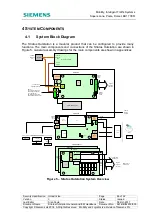
Figure 1 – Typical Semi-Integral Stratos Outstation Connectivity
The following data is transferred between the controller and the outstation via RS232
serial cable.
•
UTC control and reply signals (stage force, confirm etc) *
1
as configured by IC4
•
MOVA stage forces and confirms as configured by IC4
•
Selected controller detector states as configured by IC4, for use as UTC SCOOT
detectors and MOVA detectors
•
Faults, for display on outstation fault table and reporting to Stratos*
2
•
Controller Log, for display on outstation web interface *
2
•
IC4 configuration upload *
3
•
Remote handset text
* 1 – If connecting to ST950 controller identification and scanning should be disabled and
Enhanced Serial Protocol should be enabled. These can be setup in Status and
Configuration – Controller Monitor – Controller Port.
* 2 - When interfacing to an ST950 controller, the controller log transferred to the
outstation is a sub-set of the full log. The web interface on the ST950 should be accessed
directly to examine the controller log details.
* 3 - When interfacing to an ST950 controller, the IC4 configuration file is not transferred
to the outstation. The web interface on the ST950 should be accessed directly to upload
the IC4 configuration.
A dedicated input is provided for the controller lamp supply voltage (see section 3.9).

