


7PG2113/4/5/6 Solkor Description of Operation
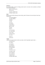
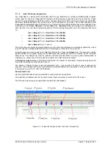
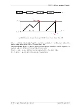
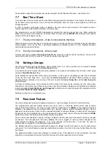
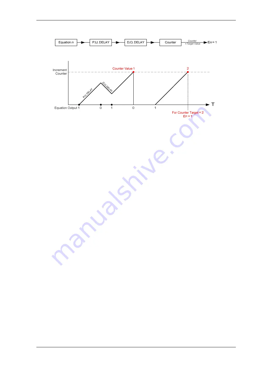
Figure 5.4-1 Sequence Diagram: Quick Logic PU/DO Timers (Counter Reset Mode Off)
When the count value =
En Counter Target
the output of the counter (En) = 1 and this value is held until the
initiating conditions are removed when En is instantaneously reset.
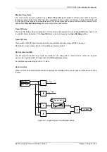
The output of E
n
is assigned in the OUTPUT CONFIG>OUTPUT MATRIX menu where it can be programmed to
any binary output (O), LED (L) or Virtual Input/Output (V) combination.
Protection functions can be used in Quick Logic by mapping them to a Virtual Input / Output.
Refer to Section 7 – Applications Guide for examples of Logic schemes.
©2010 Siemens Protection Devices Limited Chapter 1 Page 69 of 80


