


7PG2113/4/5/6 Solkor Description of Operation
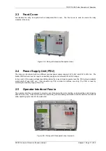
2.8
Binary Inputs
The binary inputs are operated from a suitably rated dc supply.
Relays are fitted with 3 or 6 binary inputs (BI) depending on the variant. One BI should be wired externally to the
Solkor R/Rf module to take advantage of the recording and indication functions of the numeric module. The user
can assign any binary input to any of the available functions (INPUT CONFIG > INPUT MATRIX).
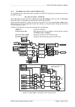
Pick-up (PU) and drop-off (DO) time delays are associated with each binary input. Where no pick-up time delay
has been applied the input may pick up due to induced ac voltage on the wiring connections (e.g. cross site
wiring). The default pick-up time of 20ms provides ac immunity. Each input can be programmed independently.
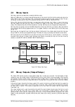
Each input may be logically inverted to facilitate integration of the relay within the user scheme. When inverted the
relay indicates that the BI is energised when no d.c. is applied. Inversion occurs before the PU & DO time delay,
see fig. 2.8-1.
Each input may be mapped to any front Fascia indication LED and/or to any Binary output contact and can also
be used with the internal user programmable logic. This allows the relay to provide panel indications and alarms.
Each binary input is set by default to be read when the relay is in both the local or remote condition. A setting is
provided to allow the user to select if each individual input shall be read when the relay is in the local or remote
condition in the INPUT CONFIG > BINARY INPUT CONFIG menu.
Event
BI 1
Binary Input 1
=1
Inverted Inputs
BI 1 inverted
BI 1 P/U Delay
Event
BI
n
Binary Input
n
=1
BI
n
inverted
BI
n
P/U Delay
INPUT CONFIG>
INPUT MATRIX
(Or gates)
Logic signals,
e.g. '51-1 Inhibit'
BI 1 D/O Delay
BI
n
D/O Delay
INPUT
CONFIG>
BINARY
INPUT
CONFIG
Figure 2.8-1 Binary Input Logic
2.9
Binary Outputs (Output Relays)
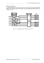
The Solkor R/Rf module provides 3 segregated voltage free normally open contacts. The functionality of these
contacts is fixed. One contact must be wired externally to the numeric module to take advantage of the recording
and indication functions of that module. Numeric modules are fitted with 5 or 8 binary outputs (BO). All outputs of
the numeric module are fully user configurable and can be programmed to operate from any or all of the available
functions.
In the default mode of operation the binary outputs of the numeric module are self reset and remain energised for
a user configurable minimum time of up to 60 seconds. If required, these outputs can be programmed to operate
as ‘hand reset’ or ‘pulsed’. If the output is programmed to be ‘hand reset’ and ‘pulsed’ then the output will be
‘hand reset’ only.
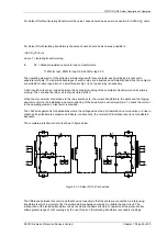
The output contacts can be used to operate the trip coils of the circuit breaker directly where the trip coil current
does not exceed the 'make and carry' contact rating. The circuit breaker auxiliary contacts or other in-series
auxiliary device must be used to break the trip coil current. It is recommended that the trip signal to the circuit
breaker is wired directly from the Solkor R/Rf module rather than via the numeric module for maximum speed and
simplicity.
©2010 Siemens Protection Devices Limited Chapter 1 Page 22 of 80


