


7PG2113/4/5/6 Data Communications
©2010 Siemens Protection Devices Limited
Chapter 4 Page 5 of 38
The RS485 electrical connection can be used in a single or multi-drop configuration. The RS485 master must
support and use the Auto Device Enable (ADE) feature. The last device in the connection must be terminated
correctly in accordance with the master device driving the connection. The relays are fitted with an internal
terminating resistor which can be connected between A and B by fitting an external wire loop between terminals
18 and 20 on the power supply module.
The maximum number of relays that can be connected to the bus is 64.
The following settings must be configured via the relay fascia when using the RS485 interface. The shaded
settings are only visible when DNP3.0 is selected.
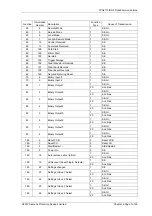
Setting name Range
Default Setting Notes
Station Address
0 … 254 (IEC60870-5-103)
0 … 247 (MODBUS)
0 … 65534 (DNP3)
0 1…
An address must be
given to identify the relay.
Each relay must have a
unique address.
COM1-RS485 Protocol
OFF, IEC60870-5-103,
MODBUS-RTU, DNP3.0
IEC60870-5-
103
As Required
Sets the protocol used to
communicate on the
RS485 connection.
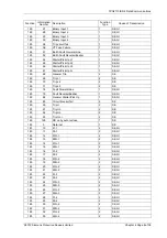
COM1-RS485 Baud
Rate
75 110 150 300 600 1200
2400 4800 9600 19200
38400
19200 As
Required
The baud rate set on all of
the relays connected to
the same RS485 bus
must be the same as the
one set on the master
device.
COM1-RS485 Parity
NONE, ODD, EVEN
EVEN
As Required
The parity set on all of the
relays connected to the
same RS485 bus must be
the same and in
accordance with the
master device.
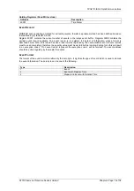
Unsolicited Mode
DISABLED ENABLED
DISABLED
As Required
Setting is only visible
when COM1 Protocol is
set to DNP3
Destination Address
0 … 65534
0
As Required
Setting is only visible
when COM1 Protocol is
set to DNP3
Figure 1.1-2 Communication to Multiple Devices from Control System using RS485


