background image


Command lists 


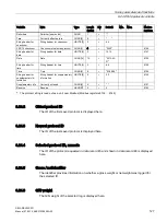
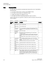
10.2 Command lists 

SIWAREX WP231 
Manual, 07/2014, A5E31238908A-02 

141


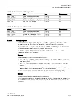
Command 
code 

Command 

Description 

Protected 

82 

Perform auto-

matic calibration 

Calculation of scale characteristic using the load cell parameters 

from data record 10. The calculated characteristic is entered 

directly in data records 3 and 4 and thus immediately enabled 

following execution of the command. The scale must be empty 

when the command is executed. 

83 

Perform calibra-

tion check 

The command calculates the theoretical digital values in•relation 

to the calibration weights using the load cell parameters from data 

record 10 and the adjustment weights 0, 1 and 2 from data record 

3. These theoretical digits are output in data record 4. The func-

tion can be used to carry out a plausibility check for the calibration 

digits in data record 3 which were determined when calibrated 

using standard weights. 


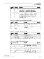
Table 10- 2  Commands 400 ... 449; log commands, statistics, logbook 

Command 
code 

Command 

Description 

Protected 

401 

Generate log 

Log current parameters relevant to the calibra-

tion 


405 

Delete log memory 

Delete all logs 

440 


Delete the logbook. Only permitted in non-

calibrated state. 


441 

Reserve 


Table 10- 3  Commands 450 ... 499: Trace commands 

Command 
code 

Command 

Description 

Protected 

451 

Trace RAM on 

Start permanent tracing 


452 

Trace RAM off 

Stop permanent tracing 


453 

Single trace RAM 

Create single trace (current state) 


454 

Delete trace RAM 

Delete tracing memory. 


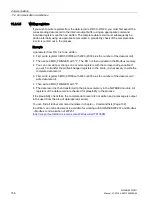
Table 10- 4  Commands 700 to 899: HMI display switching 

Command 
code 

Command 

Description 

Protected 

701 

Increased resolution  

Enable increased resolution on the main dis-

play and the SecureDisplay (x 10), for duration 

of 5 s 


705 

Display current tare weight 

Display current tare weight on main display and 

SecureDisplay 


710 

Activate standard display  

Enable standard display gross/net (main dis-

play and SecureDisplay) 


714 

N process value (no write protec-

tion) 

Display net process weight on main display, 

only permitted if OIML is not set as the regula-

tion code (main display and SecureDisplay) 

Содержание SIWAREX WP231

Страница 1: ..._______________ ___________________ ___________________ ___________________ Weighing systems Electronic weighing system SIWAREX WP231 Manual 07 2014 A5E31238908A 02 Introduction 1 Safety notes 2 Description 3 Application planning 4 Mounting 5 Connection 6 Commissioning 7 Scale parameters and functions 8 Messages 9 Command lists 10 Communication 11 Operation requiring verification 12 Technical data...

Страница 2: ...rated only by personnel qualified for the specific task in accordance with the relevant documentation in particular its warning notices and safety instructions Qualified personnel are those who based on their training and experience are capable of identifying risks and avoiding potential hazards when working with these products systems Proper use of Siemens products Note the following WARNING Siem...

Страница 3: ...plication 18 3 5 System integration in SIMATIC 19 3 6 Customer benefits 20 3 7 Scope of delivery 20 4 Application planning 21 4 1 Functions 21 4 2 Parameter assignment options 22 4 2 1 Parameter assignment with the PC 22 4 2 2 Parameter assignment with a SIMATIC Panel 23 4 2 3 Parameter assignment by means of the Modbus interface 23 5 Mounting 25 5 1 Installation guideline 25 5 2 EMC compliant set...

Страница 4: ...duction 43 7 2 Factory set parameters 43 7 3 Factory setting of the mode selector 44 7 4 Commissioning tools 44 7 5 5 minute quick start with the operator panel and the Ready for Use software 45 7 5 1 Start 45 7 5 2 Standard parameter settings 46 7 5 3 Selecting the calibration method 47 7 5 4 Defining the calibration weights 48 7 5 5 Setting calibration points 49 7 5 6 Calibrating the scale autom...

Страница 5: ...m weighing range 69 8 3 8 Calibration weights 0 1 2 and calibration digits 0 1 2 69 8 3 9 Scale interval 69 8 3 10 Zero by power on 69 8 3 11 Zero by power on when tare 0 70 8 3 12 Automatic zero adjustment 70 8 3 13 Subtractive additive tare device 70 8 3 14 Weight simulation 71 8 3 15 Decimal places for process values 71 8 3 16 Maximum tare load 71 8 3 17 Maximum negative zero setting limit powe...

Страница 6: ... 8 DR 7 interface parameters 88 8 8 1 Assignment for digital input 0 1 2 3 92 8 8 2 Input filtering hardware setting 92 8 8 3 Assignment for digital output 0 1 2 3 92 8 8 4 Response of digital outputs to faults or SIMATIC STOP 93 8 8 5 Substitute value for DQ 0 1 2 3 following fault or SIMATIC STOP 93 8 8 6 Analog output range 94 8 8 7 Analog output source 94 8 8 8 Response of analog output to fau...

Страница 7: ...11 8 18 DR 18 digital output control specifications 112 8 18 1 Overview 112 8 18 2 Specification for digital output 0 1 2 3 113 8 19 DR 30 current process values 114 8 19 1 Overview 114 8 19 2 Gross process weight 116 8 19 3 Net process weight 116 8 19 4 Tare process weight 116 8 19 5 Gross net weight 117 8 19 6 Gross net weight with increased resolution x 10 117 8 19 7 Tare weight 117 8 19 8 Gros...

Страница 8: ...ol ID to be read 126 8 24 DR 46 protocol contents 127 8 24 1 Overview 127 8 24 2 Oldest protocol ID 128 8 24 3 Newest protocol ID 128 8 24 4 Selected protocol ID numeric 128 8 24 5 Gross net identifier 128 8 24 6 G N weight 128 8 24 7 Unit of weight 129 8 24 8 Tare identification 129 8 24 9 Date time 129 8 25 DR 47 logbook 130 8 26 DR 48 date and time 2 for Modbus 131 9 Messages 133 9 1 Message ty...

Страница 9: ...4 11 2 1 3 Command mailboxes 154 11 2 1 4 Reading registers 155 11 2 1 5 Writing registers 156 12 Operation requiring verification 157 12 1 Preparing for verification 157 12 1 1 Calibration set 157 12 1 2 Scale design 157 12 1 3 Installation and parameterization of the main SecureDisplay for legal trade in the HMI 157 12 1 4 Parameterization of the scale 158 12 1 5 Adjustment and preliminary check...

Страница 10: ...2 DQ 2 93 Table 8 8 Assignment of data record 8 96 Table 8 9 Assignment of data record 9 97 Table 8 10 Assignment of data record 10 99 Table 8 11 Assignment of data record 12 101 Table 8 12 Assignment of data record 13 103 Table 8 13 Assignment of data record 14 106 Table 8 14 Selection table for process value 1 2 107 Table 8 15 Structure of status of analog output digital outputs and digital inpu...

Страница 11: ...hnical specifications Analog load cell interface connection 164 Table 13 4 Technical specifications 165 Table 13 5 Technical specifications Digital outputs 165 Table 13 6 Technical specifications Digital inputs 166 Table 13 7 Technical specifications Real time clock 166 Table 13 8 Technical specifications RS485 interface 166 Table 13 9 Technical specifications Ethernet 167 Table 13 10 Technical sp...

Страница 12: ... receiving a data record with SIWATOOL V7 53 Figure 7 10 Layout of the SIWATOOL user interface 55 Figure 7 11 Sending receiving a data record with SIWATOOL V7 56 Figure 7 12 Trace export 59 Figure 7 13 Downloading the firmware with SIWATOOL 61 Figure 8 1 Standstill monitoring 73 Figure 8 2 Step forced response of the digital low pass filter when f 2 Hz 74 Figure 8 3 Calibration digits and calibrat...

Страница 13: ...he SIMATIC S7 1200 automation system and the TIA Portal are required 1 3 Manual range of validity This manual is valid for Type designation Order No as of version SIWAREX WP231 7MH4960 2AA01 HW FS 3 FW V 2 0 0 Note This manual contains a description of all electronic weighing systems available at the date of publication We reserve the right to include a Product Information with the latest informat...

Страница 14: ...s downloads tips and tricks Our newsletter providing you with the latest information about your products A Knowledge Manager to find the right documents for you Our bulletin board where users and specialists share their knowledge worldwide You can find your local contact partner for Industry Automation and Drives Technologies in our partner database Information about field service repairs spare pa...

Страница 15: ...sted and documented in compliance with the relevant safety standards The device does usually not pose any risks of material damage or personal injury Siemens provides automation and drive products with industrial security functions that support the secure operation of plants or machines They are an important component in a holistic industrial security concept With this in mind our products undergo...

Страница 16: ...Safety notes 2 1 General safety instructions SIWAREX WP231 16 Manual 07 2014 A5E31238908A 02 ...

Страница 17: ...PU is not possible As of firmware version V1 0 4 As of firmware version V1 0 4 data records can be sent from the SIWAREX WP231 to the S7 1200 CPU and received by the latter This means that complete operation and commissioning of the scales is possible via the SIMATIC CPU or the operator panel The current Ready for Use software must be used for this in addition to the matching FW This program conta...

Страница 18: ...ations in which signals from weighing or force sensors are to be acquired and processed The SIWAREX WP231 is a very accurate electronic weighing system The SIWAREX WP231 is equipped for the following applications Non automatic weighing instrument to OIML R76 Fill level monitoring of silos and hoppers Platform scales Scales in potentially explosive atmospheres with Ex interface SIWAREX IS ...

Страница 19: ...t allows the user to configure all aspects of the automation solution and weighing application to his requirements You can create optimal solutions for small and medium sized plants by combining the suitable SIMATIC modules You can create customized or industry specific solutions in no time with the help of the configuration package available under the Ready for use application for SIMATIC Figure ...

Страница 20: ...erference frequency suppression Limit monitoring Flexible adaptation to varying requirements Easy adjustment of the scales using the SIWATOOL program Automatic calibration is possible without the need for calibration weights Module replacement is possible without recalibrating the scales Use in Ex Zone 2 ATEX approval Intrinsically safe load cell supply for Ex Zone 1 SIWAREX IS option Diagnostics ...

Страница 21: ...m or for connection to any automation system Modbus TCP IP The SIWAREX WP231 electronic weighing system can also be used in potentially explosive atmospheres Zone 2 The load cells are supplied intrinsically safe in Zone 1 applications when you use the optional Ex interface SIWAREX IS Figure 4 1 System integration in SIMATIC S7 1200 The SIWAREX WP231 can also be used in standalone mode independent ...

Страница 22: ...d you can analyze and test the processes in the scale independently of the automation system or Operator Panel with the help of the PC You can read out the diagnostic buffer from the SIWAREX module to assist you in the event analysis The figure below illustrates the structure of the individual program windows Figure 4 2 SIWATOOL overview SIWATOOL does not only offer support when you set the scale ...

Страница 23: ...Parameter assignment by means of the Modbus interface You have the option to assign the parameters with a SIMATIC panel which is connected directly to the SIWAREX module The SIWAREX module behaves like a Modbus slave in this case Loadable HMI software for a SIMATIC Panel TP700 Comfort is provided in the scope of delivery of the configuration package All SIMATIC HMI Comfort Panels can be used for d...

Страница 24: ...Application planning 4 2 Parameter assignment options SIWAREX WP231 24 Manual 07 2014 A5E31238908A 02 ...

Страница 25: ...carry out EMC planning before installing your devices in order to determine any sources of interference and include them in your considerations EMC EMC electromagnetic compatibility describes the capability of electrical equipment to operate without errors in a given electromagnetic environment without being subject to external influence and without influencing external devices in any way 5 2 2 Po...

Страница 26: ...ed metal parts support contact with special contact washers or remove the protective insulating finish on the points of contact Wherever possible avoid the use of aluminum parts for ground bonding Aluminum oxidizes very easily and is therefore less suitable for ground bonding Provide a central connection between chassis ground and the ground protective conductor system Rule 2 Proper cable routing ...

Страница 27: ...ate range of your controller use incandescent lamps or interference suppressed fluorescent lamps Rule 5 Homogeneous reference potential Create a homogeneous reference potential and ground all electrical equipment Use sufficiently dimensioned equipotential bonding conductors if potential differences exist or are expected between your system components Equipotential bonding is absolutely mandatory f...

Страница 28: ...cted to the automation system s bus system The 70 mm wide module has very low installation and cabling requirements The module is fitted on a mounting rail and the bus connection made using the slide switch The load cells power supply and serial interfaces are connected via the screw type connectors Use of the WP231 in the SIMATIC TIA Portal is described in detail in cc 11 of this manual Integrati...

Страница 29: ... by means of the screw connectors terminal block 1 to 4 24 V connection Digital input connection Analog output connection Ethernet interface connection Load cell connection Calibration bridge connection RS485 interface connection Mounting terminals for the calibration protec tion plate Digital output connection Figure 6 1 SIWAREX WP231 connection areas ...

Страница 30: ...ible number of load cells which can be connected to a WP231 Scale operation without Ex interface input resistance of load cell number of load cells 40 Ohm Scale operation without Ex interface input resistance of load cell number of load cells 50 Ohm Rules Observe the following rules when connecting analog strain gauge load cells 1 The use of a junction box SIWAREX JB junction box is required when ...

Страница 31: ...ommended that you use the cables listed in chapter Accessories Page 175 4 The shield must be connected to ground directly in the vicinity of the SIWAREX WP231 The maximum distance between the SIWAREX WP231 and the load cell applies when using the recommended cables Table 6 2 Load cell connections on the module Labeling Function Sig Measurement cable load cell Sig Measurement cable load cell Sen Se...

Страница 32: ...gnetic electrical and electromagnetic interference on the cable Interference currents on cable shielding are diverted to ground by conductive isolation rails To avoid interference as a result of these currents it is imperative to provide a low impedance connection to the ground Use only cables with protective braided shield see recommended cables of digital load cells in chapter Accessories Page 1...

Страница 33: ...Connection 6 4 Shield connection SIWAREX WP231 Manual 07 2014 A5E31238908A 02 33 Figure 6 4 Connection of strain gauge load cell s with 4 wire system ...

Страница 34: ...Connection 6 4 Shield connection SIWAREX WP231 34 Manual 07 2014 A5E31238908A 02 Figure 6 5 Connection of strain gauge load cell s with 6 wire system ...

Страница 35: ...he electronic weighing system described here has four digital outputs They are not permanently assigned to process values in the delivery state Assignment of these digital outputs to functions as well as definition of the response in the event of a fault is carried out during commissioning by parameter assignment of data record 7 The 24 V power supply for the digital outputs is provided via termin...

Страница 36: ...ronic weighing system described here has four digital inputs The digital inputs are not permanently assigned to commands in the delivery state Assignment of the digital inputs to commands is carried out during commissioning by parameter assignment of data record 7 The external 24 V switching signal is connected electrically isolated to the desired input the associated ground to terminal 2M Table 6...

Страница 37: ...tive immediately after turning on the power supply This may damage parts of the system Do not create a connection with the analog output before you know the assignment The analog output is not permanently assigned to a process value in the delivery state Assignment of the analog output to the process value as well as its response in the event of a fault is carried out during commissioning in data ...

Страница 38: ...unication partner with Modbus protocol RTU Table 6 6 Connection of RS485 serial interface Labeling Function EIA 485 T RS485 termination EIA 485 T RS485 termination EIA 485 D RS485 data line for looping through of bus signal EIA 485 D RS485 data line for looping through of bus signal EIA 485 D RS485 data line for feeding in of bus signal EIA 485 D RS485 data line for feeding in of bus signal If a S...

Страница 39: ...the following diagram Figure 6 6 Connection of Siebert display S102 The RS485 interface in the DR13 of the SIWAREX WP231 is set as follows Baud rate 9 600 bit s Character parity Even Number of data bits 8 Number of stop bits 1 The S102 is set as follows Table 6 7 Settings of Siebert display S102 Menu item Setting Meaning 1 Interface 485 RS485 interface 9 Station address 01 Address meaning Address ...

Страница 40: ...n of the Ethernet interface An RJ45 connector is used for the connection The following devices can be connected to the Ethernet interface PC with SIWATOOL service and commissioning program Operator panels or other HMI devices with Ethernet and Modbus protocol TCP IP Communication partner with Modbus protocol TCP IP ...

Страница 41: ...ially verified SIWAREX WP231 write protection must be provided to prevent the changing of data relevant to the calibration Insert a wire jumper between the module terminals P and PR for this purpose Table 6 8 Activation of write protection Labeling Function P P terminal for activation of write protection PR PR terminal for activation of write protection ...

Страница 42: ...pability the load cell connections must be protected against manipulation To achieve this mount the calibration protection plate included in the calibration set as shown in the following picture Subsequently secure the calibration protection plate using the associated terminals see Figure 6 1 SIWAREX WP231 connection areas Page 29 Figure 6 7 Mounting of the calibration protection plate See also Ov...

Страница 43: ...ality 7 2 Factory set parameters The electronic weighing system described here is provided with factory set parameters The parameters have been provided for a typical 100 kg scale based on three load cells Parameters which can be entered in or time are preset in such a way that they provide good results for most applications With these default parameters commissioning can be carried out in 5 minut...

Страница 44: ...nd alone operation without SIMATIC controller The factory setting is Operation integrated in SIMATIC Note If the switch is set to the down position while the SIWAREX module is in operation with SIMATIC the SIWAREX module will not carry out a reset upon loss of power supply to the SIMATIC CPU 7 4 Commissioning tools The following options are available for commissioning the electronic weighing syste...

Страница 45: ...ample using a TP700 Comfort Panel directly connected to the WP231 The Panel communicates directly by means of Modbus TCP IP or via the SIMATIC S7 1200 CPU To carry out the quick start select the 1 0 Setup function in the main menu and then 1 2 Quick Start You will be guided through the individual tasks for setting the most important parameters The remaining parameters are factory set in such a way...

Страница 46: ...2 Standard parameter settings The quick setup is based on the standard parameter settings The previously set parameters must therefore be reset prior to the quick setup except the Ethernet address and Modbus parameters Service mode must be switched on first Resetting to the standard parameters can then be carried out Figure 7 2 Quick start step 2 ...

Страница 47: ...ghts in the case of a calibration with weights mechanical influences of the scale construction are also partially taken into account Without weights using the technical specifications of the connected load cell s in the case of automatic calibration the accuracy of the scale is influenced by the mechanical properties to a greater extent than with calibration using reference weights With both metho...

Страница 48: ... you can define an Calibration weight 0 with the current contents of the scale With an empty scale this parameter remains as 0 kg Calibration weight 1 usually defines the first reference point of the scale characteristic A further reference point Calibration weight 2 can also be set in addition This is optional and may not be necessary depending on the mechanical properties of the scale Note that ...

Страница 49: ...t calibration weight 0 command The Calibration weight 0 defined in step 4 is now visible in the display 2 Place the Calibration weight 1 defined in step 4 on the scale construction and execute the Set calibration weight 1 command 3 If an Calibration weight 2 was selected Place Calibration weight 2 defined in step 4 on the scale construction and execute the Set calibration weight 2 command 4 Calibr...

Страница 50: ...th a silo for example to the number of clamps or feet of the silo A quadratic platform scale with a load cell at each corner has 4 support points The characteristic values of the individual load cells are required to calculate the average characteristic value of the cells The equation for the calculation is as follows characteristic of cell 1 characteristic of cell 2 characteristic of cell n n If ...

Страница 51: ...he house icon returns you to the start screen 7 5 8 Checking the scale following calibration If the scale is only used for company internal purposes a simple check is sufficient Perform the following steps 1 The scale is unloaded and shows 0 kg 2 Place a known reference weight on the scale Check the displayed value 3 If a second known reference weight is available place it on the scale in addition...

Страница 52: ...procedure is described below Figure 7 8 Quick setup with marked parameters 7 6 1 Activate service mode Service mode must be activated in order to change the calibration parameters You can find the command in the Service Commands group spanner icon 7 6 2 Load standard parameters The quick setup is based on the standard settings of the weighing module Therefore the standard parameter settings must b...

Страница 53: ...om it It is not possible to read or write individual parameters within a data record Therefore the complete data record must initially be received for every change to parameters within it The desired parameter can then be edited and the data record returned If the data record is not received the danger exists that different offline parameters will be sent to the scale and overwrite previously acti...

Страница 54: ...p file the scale is directly in the calibrated state again without a new calibration 7 6 6 Checking the scale following calibration If the scale is only used for company internal purposes a simple check is sufficient Perform the following steps 1 The scale is unloaded and shows 0 kg 2 Place a known reference weight on the scale Check the displayed value 3 If a second known reference weight is avai...

Страница 55: ...7 1 Windows and functions of SIWATOOL Control elements for SIWATOOL and operation of the scale Offline values of the SIWAREX module Parameter list of the SIWATOOL module Online values of the connected SIWAREX module Figure 7 10 Layout of the SIWATOOL user interface Sending receiving a data record is always carried out by right clicking on the data record name in the Value column in the tree struct...

Страница 56: ...l scales in your office and subsequently transfer them to the electronic weighing system during setup Data from one scale currently in operation can be exported and used to set up another scale 7 7 3 IP address for SIWAREX The factory set IP address is 192 168 0 21 This address is also preset in SIWATOOL The connection to a SIWAREX module can be established immediately The network card used must b...

Страница 57: ...ermined from the identified MAC address The Primary Setup Tool also allows the IP address of a SIWAREX module to be set changed Additional information on the Primary Setup Tool can be found in the associated manual 7 7 3 3 Setting up a network Several SIWAREX modules can be connected together in a network via a switch Via the network you can use SIWATOOL to assign parameters to and start the vario...

Страница 58: ...an select the Info item directly underneath the individual data records in the navigation tree This info card explains how the data record influences the scale behavior Tooltip If you move the mouse over a button or parameter a corresponding help text is displayed Help Click on the menu option Help to call up the SIWATOOL help The Help can be opened separately 7 7 6 Entering parameters with SIWATO...

Страница 59: ...be deleted The trace recording cycle is set in data record DR7 A dialog window is called with the Export trace data button The trace is displayed in this window as a table or graphic and the data can be exported to csv or Excel and then processed further The commands for starting and stopping are present in the Trace commands group yellow memory card icon in SIWATOOL All important measured values ...

Страница 60: ...lues You should therefore export and save the original parameter values prior to the firmware update Following the firmware update the saved data can be converted by SIWATOOL to the new firmware version Saving existing parameters Export the current parameters Select the Receive all data records function from the menu under Communication The current parameter set is then transferred to SIWATOOL Sav...

Страница 61: ...Commissioning 7 7 Service with the SIWATOOL program SIWAREX WP231 Manual 07 2014 A5E31238908A 02 61 Figure 7 13 Downloading the firmware with SIWATOOL ...

Страница 62: ... out the saved scale logs The scale logs are saved powerfail proof in the internal memory of the SIWAREX You can read out the logs with SIWATOOL using the Logs button A new window is opened and all logs present in the weighing module are read out using Refresh You can subsequently save these in EXCEL or csv format ...

Страница 63: ... enter all parameters The advantage of this solution is that you can decide the default values to be retain and the parameters that need to be adapted for your application All parameters are divided into data records DR The data records are organized in steps tasks to be implemented during commissioning or during the process Information on limitations in data record communication with SIMATIC CPUs...

Страница 64: ... parameters and modify them as required Transfer the DR 3 data record from SIWATOOL to the scales Adjust the scales Transfer the DR 3 data record from the scales to SIWATOOL Table 8 1 Assignment of data record 3 Variable Note Type Length bytes Read write protection Default Min Max Modbus registers Data record number Contains no of data record USHORT 2 r 3 1000 Length Data record length information...

Страница 65: ...1022 Calibration weight 11 FLOAT 4 rwP 100 1 maximum number range 1024 Calibration weight 2 FLOAT 4 rwP 0 1 maximum number range 1026 Calibration digits 0 determined during calibration with calibra tion weight 0 FLOAT 4 rwP 0 0 1000000 1028 Calibration digits 1 determined during calibration with calibra tion weight 1 FLOAT 4 rwP 2000 0 1000000 1030 Calibration digits 2 determined during calibratio...

Страница 66: ...ounding to 4 decimal places 5 Rounding to 5 decimal places 6 Rounding to 6 decimal places USHORT 2 rwP 0 0 6 1037 Maximum tare load Page 71 Range of the subtractive tare device in of max weighing range must not exceed 100 with regulation code OIML FLOAT 4 rwP 0 0 250 1038 Maximum negative zero setting limit power on Page 71 Negative range of the zero by power on device in of maxi mum weighing rang...

Страница 67: ... 5 USHORT 2 rwP 4 2 10 1056 Reserve 2 Reserve USHORT 2 rw 0 1057 Low pass filter limit frequency commission ing Page 75 Low pass filter 2 limit frequen cy 0 Filter disabled FLOAT 4 rw 0 tbd tbd 1058 Low pass filter number commission ing Page 75 Ordinal number of low pass filter 2 Filter ordinal number 2 1 5 USHORT 2 rw 4 2 10 1060 Mean value filter depth Page 75 Filter for digit values permitted f...

Страница 68: ... name but it may not exceed 12 characters You can enter any designation Note The scale name cannot be changed after official verification 8 3 3 Unit of weight A string with up to four digits can be specified as the unit of weight e g t kg lbs The defined unit of weight applies to all weight specifications Entries are not be converted if the unit of weight has changed Entries must be left aligned 8...

Страница 69: ...Calibration weights 0 1 2 and calibration digits 0 1 2 The calibration weights and corresponding calibration digits define the characteristic curve of the scales A detailed description can be found in section Calibration procedure Page 77 8 3 9 Scale interval The scale interval for the weighing range can be defined in accordance with EN 45501 0 0001 to 50 8 3 10 Zero by power on The scales can aut...

Страница 70: ...ow zero drifting Slow drift is assumed if the OIML R76 criteria for this are met Note If the scales are not being used in legal trade operation no OIML restrictions and this function is enabled the scales may eventually read zero after a slow drift even if they are fully loaded The function can however be limited by setting a maximum and minimum weight for zeroing 8 3 13 Subtractive additive tare ...

Страница 71: ...ccepts any external tare specification which is less than the maximum tare load percentage of maximum weighing range Tare commands are also accepted provided that the current gross weight is less than the configured maximum tare load 8 3 17 Maximum negative zero setting limit power on Zeroing means the scales are automatically set to zero when the supply voltage is switched on If zero by power on ...

Страница 72: ...uld display had there been no zeroing time of scale calibration For legal trade scales the limitation is 4 of the weighing range between the negative and positive weight for zeroing 8 3 20 Maximum positive zero setting limit semi automatically You can restrict the effect of the zeroing function by defining limits The limitation is based not on the current weight but rather on the weight which the ...

Страница 73: ...ring The diagram below illustrates how standstill monitoring works The current weight can only be registered in legal trade applications if standstill is reached Figure 8 1 Standstill monitoring 8 3 22 Standstill time Standstill monitoring checks whether the scales are correctly balanced Scale standstill is registered if the weight changes by less than a specified fluctuation in d standstill value...

Страница 74: ...tically damped low pass filter for suppressing faults The diagram below shows the step response of the filter f 2 Hz The entry 0 means that the filter is switched off A limit frequency of between 0 01 and 20 0 Hz can be specified Figure 8 2 Step forced response of the digital low pass filter when f 2 Hz The definition of the limit frequency is extremely important for the suppression of faults Defi...

Страница 75: ... value of n n max 250 weights which are recorded by the weighing module every 10 ms e g when n 10 the mean of 10 weights is calculated Every 10 ms the oldest value is discarded and the newest value included in the calculation 8 3 29 Display weighing range data The weighing range data is relevant to operation with verification capability The Display weighing range data parameter is used to define w...

Страница 76: ... display size The minimum display size defines the smallest zoom factor for the legal trade display SecureDisplay If the zoom factor for the minimum display size does not correspond to the smallest zoom factor stored in the DisplayCali xlm file in the display unit the weight value is hidden and the text Start Up is displayed ...

Страница 77: ...calibration digits for the zero point If the scales are loaded with a defined calibration weight e g 50 of the measuring range the new digital value returned by the analog to digital converter is assigned the calibration weight The characteristic curve can also be determined with a third point which must be higher than point 1 Make sure that the difference between two calibration weights is at lea...

Страница 78: ...the weighing module described here They are simply sent to SIWAREX by data record DR 3 and the scales are ready for use immediately The SIWATOOL program facilitates rapid calibration Following commissioning and calibration all data records must be read from the weighing module and saved as a scale file Identical scales can be put into operation immediately Connect the PC to the new scales and enab...

Страница 79: ...its L 0 100 kg load cell 2 mV V not loaded Approx 0 L0 Mechanical installation on load cell dead load e g 25 kg Approx 500 000 L1 Calibration weight 1 placed onto scale e g 60 kg Approx 1 200 000 L2 Calibration weight 2 placed onto scale e g 80 kg Approx 1 650 000 Lmax Nominal weight of load cell 100 kg Approx 2 000 000 Lmax 10 Rated weight approx 10 Approx 110 kg Approx 2 200 000 ...

Страница 80: ...ng the Load factory settings or Load standard parameters command The load cell parameters must subsequently be defined in data record 10 Command 82 Perform automatic calibration then uses this data and the currently applied dead load to calculate the characteristic curve of the scale The characteristic curve is active immediately Note The characteristic curve data in data record 3 active prior to ...

Страница 81: ...ion on which application the DR belongs to USHORT 2 r 101 1202 Version identifier Information on current data record version USHORT 2 r 1 1 65635 1203 Calibration digits 0 1 2 calculat ed Page 81 Calibration digits 0 calculated calibration digits calculated by auto matic calibration LONG 4 r 200000 0 1600000 1204 Calibration digits 1 calculated calibration digits calculated by auto matic calibrati...

Страница 82: ...tion 1 2 or 3 Page 83 Current tare weight tare setting FLOAT 4 rwP 0 0 Depends on specifi cation in DR 3 1218 Effective tare weight semi automatic Page 83 Current tare weight semi automatic FLOAT 4 rwP 0 0 Depends on specifi cation in DR 3 1220 Zero by power on value when switching on Page 83 Current zero by power on weight affected by switch on FLOAT 4 rwP 0 Depends on specifi cation in DR 3 Depe...

Страница 83: ...n switching on If the automatic zero by power on is configured the scale is automatically set to Zero when the power supply is switched on provided the gross weight is within the defined zero setting limits The current gross weight is saved as the zero by power on weight The zero by power on weight must be within the specified range usually 10 8 6 4 Zero weight semi automatic The zero weight comma...

Страница 84: ... 1236 Version iden tifier Information about the current data record ver sion USHORT 2 r 1 1 65635 1237 Basis of limits Gross net basis of limit values 1 and 2 0 Limit value 1 and limit value 2 are based on the gross value 1 Limit value 1 and limit value 2 are based on the net value USHORT 2 rw 0 0 1 1238 Reserve 1 Reserve USHORT 2 rw 0 0 1239 Limit value 1 ON limit value 2 ON limit value 1 OFF lim...

Страница 85: ...itch on of limit value 2 in ms TIME 4 rw 0 0 maxi mum number range 1250 Limit value 1 ON limit value 2 ON limit value 1 OFF limit value 2 OFF Page 86 Switch off point for limit value 2 of measuring range FLOAT 4 rw 0 maxi mum num ber range maxi mum number range 1252 Delay time for limit value 1 OFF delay time for limit value 2 OFF Page 86 Time for delayed switch off of limit value 2 in ms TIME 4 r...

Страница 86: ...owing specifications Switch on value switch off value Minimum value monitoring is implemented with the following specification Switch on value switch off value The diagram below illustrates the function of limit values 1 and 2 Figure 8 5 Limit value configuration 8 7 2 Delay time for limit value 1 ON delay time for limit value 2 ON If the weight reaches the specified switch value a delay time defi...

Страница 87: ...s the status empty The values are entered as a percentage of the measuring range The Empty limit always refers to the current gross weight in the scale 8 7 5 Delay time for limit value Empty ON If the weight reaches the specified switch value for scales status empty a delay time defined in ms is launched Once the delay time is over the switch for empty status changes status provided the weight sti...

Страница 88: ...bout which application the DR belongs to USHORT 2 r 101 1302 Version identifier Information about the current data record version USHORT 2 r 1 1 65635 1303 Assignment for digital input 0 1 2 3 Page 92 Assignment for input 0 Code 0 No command as signed 1 32767 Command is triggered at a rising edge 0 1 transition USHORT 2 rw 0 0 1999 1304 Assignment for input 1 Code 0 No command as signed 1 32767 Co...

Страница 89: ... 2 The relevant substitute value is activated 3 The outputs are switched on USHORT 2 rw 0 0 0 1313 Substitute value for DQ 0 1 2 3 following fault or SIMATIC STOP Page 93 Substitute value for DQ 1 following fault or SIMATIC CPU STOP BIT 0 rw 0 0 1 1314 16 Substitute value for DQ 2 following fault or SIMATIC CPU STOP BIT 0 rw 0 0 1 1314 15 Substitute value for DQ 3 following fault or SIMATIC CPU ST...

Страница 90: ...1320 Output value following fault or SIMATIC STOP Page 95 Value to be output when the OutDis signal is enabled in mA FLOAT 4 rw 0 0 24 1322 Trace recording cycle Page 95 1 10 ms 10 100 ms 100 1 s 1 000 10 s USHORT 2 rw 1 1 1000 1324 Trace storage method bit 0 0 Trace recording runs as a circular buffer 1 Trace is stopped when the trace memory is full BIT 0 rw 0 0 1 1325 16 Bit 1 Reserve BIT 0 rw 0...

Страница 91: ...ond too quickly to the signal change a minimum signal pending time can be specified The pending signal is not processed further until this time has elapsed The following values can be set Value Signal pending period Value Signal pending period 0 0 2 ms 4 1 6 ms 1 0 2 ms 5 3 2 ms 2 0 4 ms 6 6 4 ms 3 0 8 ms 7 12 8 ms 8 8 3 Assignment for digital output 0 1 2 3 A status display can be assigned to a d...

Страница 92: ...ts are usually reset following a module fault operating error or SIMATIC CPU STOP This response is the default setting If an output is to be set following a fault this response is defined using this parameter The Response of digital outputs to fault or SIMATIC STOP parameter must also be set to Output substitute value The substitute value definition is then valid Examples Table 8 6 Bit 0 defines d...

Страница 93: ...fication DR 17 Specified in mA 4 Via SIMATIC S7 I O modules 8 8 8 Response of analog output to faults or SIMATIC STOP This parameter defines the response of the analog output following a fault of the SIWAREX module or SIMATIC STOP Value Response 0 Switch off 1 Continue 2 Output configured output value e g 3 5 mA 3 Output maximum value 24 mA NAMUR 8 8 9 Start value for the analog output This parame...

Страница 94: ...TICE System can be switched to unsafe state If the analog output is to be set to a given value following a fault operating error you must ensure that this poses no danger 8 8 12 Trace recording cycle The trace function is used for the continuous recording of measured values The recording rate is defined with the parameter Value Response 1 Recording every 10 ms 10 Recording every 100 ms 100 Recordi...

Страница 95: ...col data record DR 48 must be used for the date and time Procedure Set the date and time Transfer the data record to the scales Table 8 8 Assignment of data record 8 Variable Note Type Length bytes Rw Default Min Max Modbus registers Data record number Contains no of data record USHORT 2 r 8 1330 Length Data record length information USHORT 2 r 16 1331 Application Information about which applica t...

Страница 96: ...T 2 r 101 1342 Version identi fier Information on the current data record version USHORT 2 r 1 1 65635 1343 Order No header Maximum and current string length for the order number UBYTE 2 2 r 16 16 1344 Order No Order number of the module 7MH CHAR 16 16 r 7MH 1345 Serial number header String header UBYTE 2 2 r 12 12 1352 Serial number Serial number XXX00001 CHAR 12 12 r 1353 Firmware type header St...

Страница 97: ...EX WP231 Manual 07 2014 A5E31238908A 02 97 Variable Note Type Length bytes Rw Default Min Max Modbus registers DRAM memory Flash memory USHORT 2 r 0 1368 Flash memory MRAM memory USHORT 2 r 0 1369 MRAM memory Memory type USHORT 2 r 0 1370 Reserve 1 0 FLOAT 4 r 0 1371 ...

Страница 98: ...ier Information on current data record version USHORT 2 r 1 1 65635 1403 Number of load cells1 Number of analog load cells in ternal variable USHORT 2 rw 1 1 6 1404 50 60 Hz tog gling Page 100 50 60 Hz toggling USHORT 2 rw 0 0 1 1405 Number of support points Page 100 1 Number of support points USHORT 2 rw 0 0 8 1406 Reserve USHORT 2 rw 0 0 0 1407 Load cell char acteristic value Page 100 1 Characte...

Страница 99: ...ts is equal to the total number of load cells and fixed support points 8 11 4 Load cell characteristic value The load cell characteristic value is required to correctly interpret the output voltage from the load cell This specification is also necessary for determining load cell overload The exact value can be entered if the measurement log for the load cell is available The mean value can be ente...

Страница 100: ... 3 USHORT 2 r 0 FF 1506 Device MAC address 4 USHORT 2 r 0 FF 1507 Device MAC address 5 USHORT 2 r 0 FF 1508 Device MAC address 6 USHORT 2 r 0 FF 1509 Port MAC address Page 102 Port MAC address 1 USHORT 2 r 0 FF 1510 Port MAC address 2 USHORT 2 r 0 FF 1511 Port MAC address 3 USHORT 2 r 0 FF 1512 Port MAC address 4 USHORT 2 r 0 FF 1513 Port MAC address 5 USHORT 2 r 0 FF 1514 Port MAC address 6 USHOR...

Страница 101: ...is MAC address cannot be changed by the user 8 12 4 IP address Assign the IP address using the Primary Setup Tool SIWATOOL or via the SIMATIC see chapter IP address for SIWAREX Page 56 8 12 5 Subnet mask Assign the subnet mask of your network 8 12 6 Gateway If a gateway is used between the SIWAREX WP231 and the communication partner enter the gateway address here If a gateway is not present enter ...

Страница 102: ...s to USHORT 2 r 101 1560 Version identifier Information on current data record version USHORT 2 r 1 1 65635 1561 RS485 pro tocol Page 104 0 No protocol 1 MODBUS RTU 2 SIEBERT display USHORT 2 rw 1 0 2 1562 RS485 baud rate Page 104 0 1 200 bps 1 2 400 bps 2 9 600 bps 3 19 200 bps 4 38 400 bps 5 57 600 bps 6 115 000 bps USHORT 2 rw 3 0 6 1563 RS485 char acter parity Page 105 Character parity 0 Even ...

Страница 103: ...ddress for Vito mod ule USHORT 2 rw 20 1 255 1565 Decimal place for Siebert indicator Page 105 Decimal place for Siebert display SHORT 2 rw 0 1566 MODBUS RTU frame delay Delay time for response with MODBUS RTU in ms RS485 USHORT 2 rw 0 1567 Reserve 3 Reserve FLOAT 4 rw 0 1568 8 13 2 RS485 protocol This parameter defines the protocol for communication via the RS485 interface Value Protocol 0 No com...

Страница 104: ... the number of data bits for the RS485 interface Value Data bits 0 7 1 8 8 13 6 RS485 number of stop bits This parameter defines the number of stop bits for the RS485 interface Value Stop bits 0 1 1 2 8 13 7 RS485 Modbus address This parameter defines the Modbus address 1 to 230 for communication via the RS485 interface with the Modbus protocol 8 13 8 Decimal place for Siebert indicator A fixed de...

Страница 105: ...Type Length bytes Rw Default Min Max Modbus registers Data record number Contains no of data rec ord USHORT 2 r 14 1570 Length Data record length infor mation USHORT 2 r 16 1571 Application Information about which application the DR belongs to USHORT 2 r 101 1572 Version identifier Information on current data record version USHORT 2 r 1 1 65635 1573 Selection of process value 1 2 Page 107 Selectio...

Страница 106: ...30 FLOAT Tare process 3 30 FLOAT Legal trade G N weight 4 30 FLOAT G N weight_x10 5 30 FLOAT Legal trade tare weight 6 30 FLOAT Gross 2 process value 7 30 FLOAT Net 2 process value 8 30 FLOAT Unfiltered digit value 9 31 LONG Filtered digit value 10 31 LONG Filtered digit value 2 11 31 LONG Refresh counter 12 30 USHORT Status of analog output digital outputs and digital inputs 13 31 WORD BYTE Table...

Страница 107: ...mation about which application the DR belongs to USHORT 2 r 101 1580 Version identifier Information on current data record version USHORT 2 r 1 1 65635 1581 Specification of tare weight 1 2 3 Page 108 Tare setting memory 1 FLOAT 4 rw 0 0 Depends on specification in DR 3 1582 Tare setting memory 2 FLOAT 4 rw 0 0 Depends on specification in DR 3 1584 Tare setting memory 3 FLOAT 4 rw 0 0 Depends on s...

Страница 108: ...Scale parameters and functions 8 15 DR 15 tare settings SIWAREX WP231 108 Manual 07 2014 A5E31238908A 02 ...

Страница 109: ...tes Rw Default Min Max Modbus registers Data record number Contains no of data record USHORT 2 r 16 1592 Length Data record length information USHORT 2 r 16 1593 Application Information about which applica tion the data record belongs to USHORT 2 r 101 1594 Version identi fier Information about current data record version USHORT 2 r 1 1 65635 1595 Weight simula tion specifica tion Page 110 Weight ...

Страница 110: ...the data record to the scales Table 8 18 Assignment of data record 17 Variable Note Type Length bytes Rw Default Min Max Modbus registers Data record number Contains no of data record USHORT 2 r 17 1600 Length Data record length information USHORT 2 r 16 1601 Application Information about which application the data record belongs to USHORT 2 r 101 1602 Version identi fier Information about current...

Страница 111: ...Table 8 19 Assignment of data record 18 Variable Note Type Length bytes Rw Default Min Max Modbus registers Data record number Contains no of data record USHORT 2 r 18 1608 Length Data record length infor mation USHORT 2 r 12 1609 Application Information about which application the DR belongs to USHORT 2 r 101 1610 Version identi fier Information on current data record version USHORT 2 r 1 1 65635...

Страница 112: ... 1 1612 9 Bit 8 Reserve BIT 0 rw 0 0 1 1612 8 Bit 9 Reserve BIT 0 rw 0 0 1 1612 7 Bit 10 Reserve BIT 0 rw 0 0 1 1612 6 Bit 11 Reserve BIT 0 rw 0 0 1 1612 5 Bit 12 Reserve BIT 0 rw 0 0 1 1612 4 Bit 13 Reserve BIT 0 rw 0 0 1 1612 3 Bit 14 Reserve BIT 0 rw 0 0 1 1612 2 Bit 15 Reserve BIT 2 rw 0 0 1 1612 1 Reserve 1 Reserve USHORT 2 rw 0 1613 8 18 2 Specification for digital output 0 1 2 3 Digital out...

Страница 113: ...e 8 20 Assignment of data record 30 Variable Note Type Length bytes Rw Default Min Max Modbus registers Data record number Contains no of data record USHORT 2 r 30 3000 Length Data record length infor mation USHORT 2 r 60 3001 Application Information about which application the data record belongs to USHORT 2 r 101 3002 Version identi fier Information about current data record version USHORT 2 r 1...

Страница 114: ...nalog output fault BIT 0 r 0 3005 4 Reserve BIT 0 r 0 3005 3 Startup Restore point startup or restore has taken place is deleted again after 5 seconds BIT 0 r 0 3005 2 Fault status Operating fault BIT 0 r 0 3005 1 1000 Group message Operating error present BIT 2 r 0 3006 16 Reserve BIT 0 r 0 3006 15 1104 Undervoltage BIT 0 r 0 3006 14 1105 Overload BIT 0 r 0 3006 12 1106 Underload BIT 0 r 0 3006 1...

Страница 115: ...id Page 117 Net weight after dig filter 2 process value FLOAT 4 r 0 3022 Refresh coun ter for process values Page 117 Refresh counter incremented by 1 if weight values were changed USHORT 2 r 0 3024 Reserve 1 Reserve SHORT 2 r 0 3025 Last report ID Page 117 Last generated report ID ULONG 4 r 0 3026 Reserve 3 Reserve FLOAT 4 r 0 3028 8 19 2 Gross process weight The current gross weight Values are r...

Страница 116: ...s to the scale interval specified in data record DR 3 8 19 8 Gross process weight commissioning aid The current gross weight Values are rounded as specified in data record DR 3 with the Decimal places for process values Page 71 parameter 8 19 9 Net process weight commissioning aid The current net weight Values are rounded as specified in data record DR 3 with the Decimal places for process values ...

Страница 117: ...o USHORT 2 r 101 3302 Version identifier Information about current data record version USHORT 2 r 1 1 65635 3303 Unfiltered digit value Page 119 Unfiltered digit value of AD con verters digital load cells LONG 4 r 0 3304 Filtered digit value Page 119 Filtered digit value of AD convert ers digital load cells after dig filter 1 LONG 4 r 0 3306 Filtered digit value com missioning aid Page 119 Filtere...

Страница 118: ...mented by 1 if weight values were changed USHORT 2 r 0 3313 Current load cell signal in mV Page 120 Currently measured load cell signal FLOAT 4 r 0 3314 8 20 2 Unfiltered digit value The unfiltered digit value is the internal measured value immediately before filtering 8 20 3 Filtered digit value The filtered digit value is the internal measured value immediately after filtering 8 20 4 Filtered di...

Страница 119: ...nt status of the digital outputs 8 20 8 Refresh counter for process values Measured values are calculated every 10 ms in the SIWAREX module A counter is incremented by 1 each time Once the counter reaches the value 65536 it starts again from zero The counter can be used as a time stamp for data record DR 30 8 20 9 Current load cell signal in mV Display of currently measured signal voltage of the l...

Страница 120: ...er Information about current data record version USHORT 2 r 1 1 65635 3503 5000 Data or operating error exists BIT r 0 0 1 3504 16 5001 Command code or data record unknown BIT r 0 0 1 3504 15 5002 Command or data change not possible because write protection is active BIT r 0 0 1 3504 14 5003 Leaving calibration mode not possible BIT r 0 0 1 3504 13 5004 Command or data transmission only available ...

Страница 121: ... Scale interval rounding not plausible BIT r 0 0 1 3506 6 7011 Filter parameter not plausible BIT r 0 0 1 3506 5 7013 Interface assignment for verifiable HMI not plausible BIT r 0 0 1 3506 4 Reserve BIT r 0 0 1 3506 3 Reserve BIT r 0 0 1 3506 2 7016 Parameter assignment of analog output not plausible BIT r 0 0 1 3506 1 7017 MAC address cannot be changed BIT r 0 0 1 3607 16 7018 Error in IP mask BI...

Страница 122: ...e system 8 21 3 Modbus RTU error code The error code is displayed here of the error which was triggered last as a result of a command at the Modbus RTU interface 8 21 4 Modbus Ethernet error code The error code is displayed here of the error which was triggered last as a result of a command at the Modbus Ethernet interface 8 21 5 SIWATOOL error code The error code is displayed here of the error wh...

Страница 123: ... software Table 8 23 Assignment of data record 34 Variable Note Type Length bytes Rw Default Min Max Modbus registers Data record number Contains no of data record USHORT 2 r 34 4000 Length Data record length information USHORT 2 r 26 4001 Application Information about which application the DR belongs to USHORT 2 r 101 4002 Version iden tifier Information about current data record version USHORT 2...

Страница 124: ...R 9 Current calibration regulation From DR 9 Serial number of module From DR 9 Below are some display examples Commands are used to toggle display values The values to be displayed are hidden if for example a fault is pending or a value is outside the valid display range Value designation Blank Display value Unit of weight from DR 3 Weight Tare 0 NET 2 2 0 5 0 kg Weight Tare 0 B 0 0 3 t Operator e...

Страница 125: ...ssignment of data record 45 Variable Note Type Len gth byt es Rw Default Min Max Modbus regis ters Data record number Contains no of data record USHORT 2 r 45 6000 Length Data record length information USHORT 2 r 28 6001 Application Information about which applica tion the DR belongs to USHORT 2 r 101 6002 Version identifier Information about current data record version USHORT 2 r 1 1 65635 6003 R...

Страница 126: ...try available ULONG 4 r 0 1 4 294 967 295 6106 Selected protocol ID numeric ID of subsequent protocol entry 0 No entry available ULONG 4 r 0 1 4 294 967 295 6108 Reserve Reserve UBYTE 2 2 r 12 12 6110 Reserve Reserve CHAR 12 12 r 0 1 4294967295 6111 Reserve Reserve UBYTE 2 2 r 12 12 6117 Reserve Reserve CHAR 12 12 r 0 1 4294967295 6118 Reserve Reserve UBYTE 2 2 r 12 12 6124 Reserve Reserve CHAR 12...

Страница 127: ... 23 59 59 6156 String header for supplementary in formation String header for supplementary information UBYTE 2 2 r 2 2 6100 Supplementary info Currently not used CHAR 4 4 r 6161 Reserve Reserve USHORT 2 r 0 6163 1 The protocol string is read out as a unit over Modbus Modbus registers 6132 6145 8 24 2 Oldest protocol ID The ID of the first saved protocol is displayed here 8 24 3 Newest protocol ID...

Страница 128: ...nit of weight of the selected log is displayed here 8 24 8 Tare identification The tare identification of the selected log is displayed here The identification shows whether the tare has been entered by the user semi automatically or whether it is a specified tare 8 24 9 Date time The date and time of the selected log are displayed here ...

Страница 129: ...Information about which appli cation the data record belongs to USHORT 2 r 101 3902 Version identifier Information about current data record version USHORT 2 r 1 1 65635 6903 String header for ID of oldest logbook entry String header UBYTE 2 2 r 8 8 6904 ID of oldest logbook entry ID of first logbook entry CHAR 8 8 r 0 1 999999 99 6905 String header for ID of most recent logbook entry String heade...

Страница 130: ...module Table 8 27 Assignment of data record 48 Variable Note Type Len gth byt es Rw Default Min Max Modbus registers Data record number Contains no of the data record USHORT 2 r 48 6960 Length Data record length information USHORT 2 r 24 6961 Application Information on which application the data record belongs to USHORT 2 r 101 6962 Version iden tifier Information on the current data record versio...

Страница 131: ...Scale parameters and functions 8 26 DR 48 date and time 2 for Modbus SIWAREX WP231 Manual 07 2014 A5E31238908A 02 131 ...

Страница 132: ......

Страница 133: ...he sent command in its current operating state Technology errors Technology errors occur spontaneously due to the process flow of a weighing Status bits on the other hand are not messages The status displays describe the status of the scale during normal operation and can be monitored or evaluated at any time 9 2 Message paths You can read out the messages using different paths You define the path...

Страница 134: ...scale parameters This facilitates the detection analysis and correction of errors in the system 9 4 Detecting messages with the help of FB SIWA All messages of the SIWAREX module can be completely detected and processed in the controller with the help of the SIWAREX WP231 function block The messages can be evaluated directly in a signaling system by means of a bit signaling area in the scale data ...

Страница 135: ...voltage at sensor cables 1105 Overload 1105 Overload of scale ca 110 1106 Underload 1106 Underload of scale ca 10 1107 Legal trade display failure 1107 The SecureDisplay legal trade display no longer communicates with the module 9 5 2 Technology error message list Technology error code 2000 to 4999 Error code Description and remedy 2000 Technology error exists 2000 Group message at least one techn...

Страница 136: ... 6002 Logging is not possible because the limits for the minimum weight or maximum weight were not observed 7000 Permitted number range violated 7000 The permitted number range such as for weight values was violat ed 7001 Regulation code not known 7001 Regulation code for application requiring official calibration not known 7002 Specifications of string lengths not plausi ble 7002 The string heade...

Страница 137: ...1 Limit 1 responded LED 23 Limit 2 responded LED 3 Limit 3 responded empty limit LED 4 Standstill status LED 5 0 d zero status LED 6 Max Max violated with NAW Max 9e LED 7 Parameter input blocked write protection LED 8 Not used LED 19 LC Load cell s OK Load cell s faulty LED 10 Not used LED 11 Not used LED 12 Not used LED 13 Not used LED 14 Not used LED 15 Not used LED 16 AQ Analog output active A...

Страница 138: ...t 0 active LED 6 DI 1 Digital input 1 active LED 7 DI 2 Digital input 2 active LED 8 DI 3 Digital input 3 active LED 9 Not used LED 10 Not used LED 11 Rx Tx RS485 communication active LED 12 Not used LED 13 DQ 0 Digital output 0 active LED 14 DQ 1 Digital output 1 active LED 15 DQ 2 Digital output 2 active LED 16 DQ 3 Digital output 3 active ...

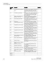
Страница 139: ... data record DR 7 A data or command error is signaled if a command cannot be executed or if the sent data record is rejected Detailed descriptions of the commands can be found in the following command lists Table 10 1 Commands 1 99 Service commands Page 140 Table 10 2 Commands 400 449 log commands statistics logbook Page 141 Table 10 3 Commands 450 499 Trace commands Page 141 Table 10 4 Commands 7...

Страница 140: ...orks status During this process all parameters and saved data including protocol memory and logbook as well as the restore point are loaded with the default values all message buffers diagnostics buffer trace memory etc are reset P 12 Load standard parameters Like Load factory settings command code 11 but interface settings for Ethernet and Modbus RTU are not reset to the factory setting P 31 Load...

Страница 141: ...0 449 log commands statistics logbook Command code Command Description Protected 401 Generate log Log current parameters relevant to the calibra tion 405 Delete log memory Delete all logs P 440 Delete the logbook Only permitted in non calibrated state 441 Reserve Table 10 3 Commands 450 499 Trace commands Command code Command Description Protected 451 Trace RAM on Start permanent tracing 452 Trace...

Страница 142: ...ant 3 Acts on the legal trade display SecureDisplay Enables version 1 for display size and position according to DisplayCali xml file 864 Legal trade display for variant 4 Acts on the legal trade display SecureDisplay Enables version 1 for display size and position according to DisplayCali xml file 865 Legal trade display for variant 5 Acts on the legal trade display SecureDisplay Enables version ...

Страница 143: ...utomatic 1011 Tare Taring semi automatic 1012 Delete tare Delete current tare weight 1013 Tare specification 1 valid Activate specification tare weight 1 1014 Tare specification 2 valid Activate specification tare weight 2 1015 Tare specification 3 valid Activate specification tare weight 3 1016 SIMATIC tare specification Specified tare weight from SIMATIC I O interface See also Integration in SIM...

Страница 144: ...mmand list see Command lists Page 140 2000 X Reading of a data record X corresponds to the data record number Example Data record 3 transmitted by SIWAREX module to SIMATIC CPU 2000 3 command code 2003 4000 X Writing of a data record X corresponds to the data record number Example Data record 3 transmitted by SIMATIC CPU to the SIWAREX module 4000 3 command code 4003 7001 Read all data Read all da...

Страница 145: ...ernative function blocks without data record communication the current process values of the scale weight status can be read and commands taring zeroing etc can be sent Complete commissioning from the CPU or HMI is not possible since the required parameters such as the calibration weight cannot be sent This must be carried out on site using SIWATOOL Table 11 1 Memory requirements of the function b...

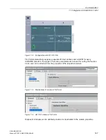
Страница 146: ...he SIWAREX WP231 is integrated as standard in the hardware profile as an S7 1200 technology module For TIA Portal V11 an HSP is available for integration at Hardware Support Package http support automation siemens com WW view de 73514020 Figure 11 1 Configuration in the TIA Portal HW catalog The module can be positioned directly next to the S7 1200 CPU using drag and drop ...

Страница 147: ...ate I O start address and a HW ID for every SIWAREX present in the project These two parameters are relevant for calling the function block and can be obtained from the properties of the respective module Figure 11 3 Start address of module in TIA Portal Figure 11 4 HW ID of module in TIA Portal Diagnostic interrupts can be optionally enabled or deactivated in the module properties ...

Страница 148: ...ly in the control program Figure 11 5 Calling of WP231PR block in user program Function block parameter Description ADDR Start address WP231 see Creating the hardware configuration Page 146 HW_ID HW ID WP231 see Creating the hardware configura tion Page 146 DB_NO Number of FB internal instance DB LIFEBIT Optional status bit can be used to monitor communica tion The generated instance DB DB231 in t...

Страница 149: ...s shown in the graphics a command mailbox always consists of a command code Int and four bits Bool A command is set by entering the desired command code in the i_CMD_CODE parameter and setting the respective command trigger bo_CMD_TRIGGER The status bits bo_CMD_InProgress command being processed bo_CMD_FinishedOk command finished without errors and bo_CMD_FinishedError command rejected or finished...

Страница 150: ...le using command code 1 see chapter Command lists Page 139 The variable i_CMD_CODE must therefore be assigned the value 1 and the associated bo_CMD_TRIGGER set to TRUE Subsequently the module is directly in service mode DIAG LED flashes green i_CMD_CODE 1 bo_CMD_TRIGGER TRUE Since only complete data records can be read or written it is recommendable to now read data record 3 into the CPU This is c...

Страница 151: ..._ERRORS Operating error according to Message list Page 134 TECHNOLOGICAL_ERRORS Technological errors according to Message list Page 134 DATA_CMD_ERROR_1 Data command error according to Message list Page 134 DATA_CMD_ERROR_2 Data command error according to Message list Page 134 DATA_CMD_ERROR_3 Data command error according to Message list Page 134 DATA_CMD_ERROR_4 Data command error according to Me...

Страница 152: ...bo_SFBError Runtime error during transmission of data record bo_RdPerError Reading of I O data failed bo_LifeBitError SIWAREX no longer responds bo_StartUpError Command was sent although StartUp is still TRUE bo_WrongFW Data record version does not match the firmware bo_InvalidCMD An invalid command code was sent bo_DataOperationError Synchronous data operation error has occurred bo_StartUp Startu...

Страница 153: ... This description is valid for communication via Modbus RTU and Modbus TCP IP The standardized MODBUS protocol is used for communication The master function is always in the connected communication partner while the SIWAREX module is always the slave Data transfer is bidirectional The master function is always in the connected module which controls the communication with corresponding requests to ...

Страница 154: ...us standard Afterwards the master requests the data record DR 32 to check which process related data or operator errors exist 11 2 1 2 Data record concept The register assignment is an image of the data records The chapter Scale parameters and functions Page 63 describes the data records variables and functions including the register addresses The data records are always checked as complete data p...

Страница 155: ...y be read as current values DR 30 to DR 34 If you wish to read the registers from the data records DR 3 to DR 29 you must first export these as a complete data record to the internal output buffer All Modbus registers of the individual parameters can be found in chapter Scale parameters and functions Page 63 Example A parameter is to be read from data record 3 DR 3 First write register CMD3_CODE w...

Страница 156: ...n the Modbus memory You can now write or change one or more registers with the corresponding variable If you wish to transfer the written changed registers to the scale it is necessary to write the complete data record First write register CMD3_CODE with 4003 4000 plus the number of the data record write data record Then write CMD3_TRIGGER with 1 The data record is then transferred to the process ...

Страница 157: ...sive markers M green and red You can prepare the scale verification using the calibration set 12 1 2 Scale design If you wish to use the scale in operation requiring verification the design must correspond to the conditions specified in the construction license Therefore you should already take the specifications of the construction license into account when configuring and designing the scale 12 ...

Страница 158: ...on either These are identified in the command table by P 12 1 5 Adjustment and preliminary checking of the scale During commissioning the scale adjustment detailed description Calibration procedure Page 77 is carried out following input of the scale parameters Depending on the type and the area of use the scope of operations for checking the measuring properties of the scale prior to the verificat...

Страница 159: ...ables using buttons 1 to 5 Show smallest possible display using command button In the area of the calibration data display Advanced scale parameters 4 of 4 the smallest zoom factor is applied which still results in a readily readable display size Following the verifi cation users can only select larger windows for the calibration display Switch over contents of the SecureDis play the display switc...

Страница 160: ...ation electronics must agree with the requirements in the EC construction license The currently valid version can be called on the SecureDisplay Call up the main menu in the main display function key with the open end wrench Select the Calibration check submenu in the main menu Select the Version and variables check submenu in the Calibration check submenu Activate the Display SIWAREX firmware rel...

Страница 161: ...ruction license 6 Checking of the serial number of the evaluation electronics The serial number of the evaluation electronics used shown at top right in the SecureDisplay must agree with the ID label The serial number of the evaluation electronics used can also be called on the SecureDisplay Call up the main menu in the main display function key with the open end wrench Select the Calibration chec...

Страница 162: ...en end wrench Select the Calibration check submenu in the main menu Select the Scale check submenu in the Calibration check submenu Check with the Tare setting or Delete tare command 9 Checking of the parameter disabling calibration bridge The calibration bridge must be inserted on the weighing module You can check the calibration bridge using the specific symbol at the bottom right in the main di...

Страница 163: ...ply Rated voltage 24 V DC Static low high limits 19 2 V DC 28 8 V DC Dynamic low high limits 18 5 V DC 30 2 V DC Non periodic overvoltages 35 V DC for 500 ms with a recovery time of 50 s Maximum current consumption 200 mA with 24 V DC Typical power loss of the module 4 5 W Power supply from SIMATIC S7 backplane bus Table 13 2 Technical specifications Power supply from SIMATIC S7 backplane bus Curr...

Страница 164: ... 2 3 Short circuit and overload protection Yes Connection 6 wire Sensor voltage monitoring 0 3 V Min DMS input resistance without Ex i interface SIWAREX IS 40 Ω with Ex i inter face SIWAREX IS 50 Ω min DMS output resistance 4 100 Ω Temperature coefficient range 5 ppm K v E Temperature coefficient zero point 0 1 μV K Linearity error 0 002 Measured value filtering Low pass Electrical isolation 500 V...

Страница 165: ...arity error 0 05 Electrical isolation 500 V AC Cable length max 100 m twisted and shielded Figure 13 1 Current ranges for signal level to Namur recommendation NE43 Digital outputs DQ The set value is output at the digital output in case of a fault or SIMATIC CPU stop A freewheeling diode has to be installed at the consumer with inductive loads at the digital output Table 13 5 Technical specificati...

Страница 166: ...g 0 2 0 4 0 8 1 6 3 2 6 4 and 12 8 ms Electrical isolation 500 V DC Real time clock Table 13 7 Technical specifications Real time clock Accuracy at 25 C 60 s month Buffered period typ 10 days at 25 C min 6 days at 40 C RS485 interface Table 13 8 Technical specifications RS485 interface Standard EIA 485 Baud rate up to 115 kbps Data bits 7 or 8 Parity even odd none Stop bits 1 or 2 Terminating resi...

Страница 167: ... 3 Transmission rate 10 100 Mbps determined automatically Electrical isolation 1 500 V AC Transfer protocol TCP IP Modbus TCP see 1 Autonegotiation Yes Auto MDI X Yes Cable lengths Cat 5e UTP cable unshielded max 50 m Cat 5e SF UTP cable shielded max 100 m Dimensions and weights Table 13 10 Technical specifications Dimensions W x H x D 70 x 100 x 75 mm Weight 300 g ...

Страница 168: ...ration IEC 61131 2 IEC 60068 2 27 Test Ea 150 m s2 approx 15 g half sine Duration 11 ms Quantity 3 each per axis in negative and positive direction Vibration load during transport IEC 60068 2 6 Test Fc 5 to 8 4 Hz 3 5 mm out 8 4 Hz 500 Hz 9 8 m s2 10 cycles per axis 1 octave min Shock load during transport IEC 60068 2 27 Test Ea 250 m s2 25G half sine Duration 6ms Quantity 1 000 each per axis in n...

Страница 169: ...r connection serves only a functional earth to dissipate interfer ence currents IP degree of protection IP 20 to IEC 60529 Protection against contact with standard probe Protection against solid bodies with diameters in excess of 12 5mm No special protection against water Air gaps and creepage distanc es IEC 60664 IEC 61131 2 IEC 61010 1 UL 508 CSA C22 2 No 145 EN 50156 1 Overvoltage category II P...

Страница 170: ...netic fields Class A industrial environment EN 61000 6 4 IEC CISPR 16 2 3 2008 30 230 MHz 40 dB μV m Q 230 1 000 MHz 47 dB μV m Q Emission on power supply cables 24 V Class A Industrial environment EN 61000 6 4 IEC CISPR 16 2 1 2010 EN 55016 2 1 2009 Class A Industrial environment 0 15 0 5 MHz 79 dB μV Q 0 15 0 5 MHz 66 dB μV M 0 5 30 MHz 73 dB μV Q 0 5 30 MHz 60 dB μV M Emission conducted Etherne...

Страница 171: ... cables EN 61000 4 5 IEC 61131 2 NAMUR NE21 EN 61326 1 kV symmetrical1 2 kV asymmetrical HF irradiation amplitude modulated IEC61000 4 3 NAMUR NE21 OIML R76 EN 45501 3 80 to 2 000 MHz 12 V m Mod 80 AM with 1 kHz Note In the ranges 87 108 MHz 174 230 MHz and 470 790 MHz 3 V m HF irradiation cell phone frequencies IEC 61000 4 3 900 MHz 5 MHz 1 89 Ghz 10 MHz 10 V m HF voltage on data signal and power...

Страница 172: ...ipitation Table 13 16 Climatic requirements Comments Ambient conditions Application areas Operating temperature vertical installation in S7 1200 10 60 C horizontal installation in S7 1200 10 40 C Operation with verifi cation capability 10 40 C Storage and transport temperature 40 70 C Relative humidity 5 95 No condensation corresponds to relative humidity RH stress level 2 to DIN IEC 61131 2 Conta...

Страница 173: ... WW siteid csius extranet sta ndard groupid 4000002 objaction cssearch content adsearch 2Fadsearch 2Easpx Note The currently valid approvals for SIWAREX WP231 are to be found on the module rating plate CE approval http support automation siemens com WW view de 65692972 cULus approval http support automation siemens com WW view de 74442065 In preparation In accordance with 2004 108 EC ATEX product ...

Страница 174: ...Technical data 13 3 Approvals SIWAREX WP231 174 Manual 07 2014 A5E31238908A 02 ...

Страница 175: ...use project for TIA portal and TP 700 Comfort operator panel Calibration plate for covering the connection terminals Tags for ID labels Self adhesive markers M green and red Guidelines for verification verification certifi cates and approvals templates for ID labels SIWAREX WP231 Manual 7MH4960 2AY10 SIWAREX WP231 manual in various languages Free download from the Internet WP231 manuals http suppo...

Страница 176: ...rinsically safe connection of load cells including manual suitable for the load cell groups SIWAREX CS U M FTA and P With short circuit current 199 mA DC 7MH4 710 5BA With short circuit current 137 mA DC 7MH4 710 5CA Cable optional Cable Li2Y 1 x 2 x 0 75 ST 2 x 2 x 0 34 ST CY To connect SIWAREX CS U M P A WP231 to the junction box JB extension box EB or Ex interface Ex I or between two JBs for fi...

Страница 177: ...s can be destroyed by voltages well below the threshold of human perception These static voltages develop when you touch a component or electrical connection of a device without having drained the static charges present on your body The electrostatic discharge current may lead to latent failure of a module that is this damage may not be significant immediately but in operation may cause malfunctio...

Страница 178: ...r body the workplace and packaging are grounded This prevents electrostatic charge Avoid direct contact As a general rule only touch electrostatic sensitive devices when this is unavoidable e g during maintenance work Handle the modules without touching any chip pins or PCB traces In this way the discharged energy can not affect the sensitive devices Discharge your body before you start taking any...

Страница 179: ...anel HW Hardware NAWI Non automatic weighing instrument NAW Non automatic scales OIML Organisation Internationale de Metrologie Legale OP Operator Panel SIMATIC PC Personal computer pT Preset tare predefined tare weight with manual taring RAM Random access memory PLC Programmable logic controller STEP 7 Programming device software for SIMATIC S7 T Tare weight TM Technology module TP Touch Panel SI...

Страница 180: ...List of abbreviations SIWAREX WP231 180 Manual 07 2014 A5E31238908A 02 ...

Страница 181: ...nual 07 2014 A5E31238908A 02 181 Index A Additional Support 14 C Customer Support Hotline 13 E ESD guidelines 177 G Guidelines ESD guidelines 177 H Hotline 13 I Internet 14 S Scope of delivery 20 Service 14 Support 14 ...

Страница 182: ...Index SIWAREX WP231 182 Manual 07 2014 A5E31238908A 02 ...

Отзывы: