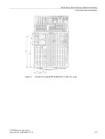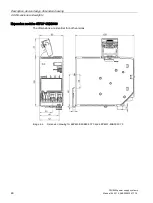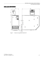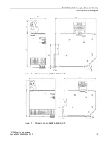
Description, device design, dimension drawing
2.7 Signaling contact/control contact
PSU8600power supply systems
38
Manual, 04.2016, A5E35883207-7-76
2.7.2
Buffer modules
Note
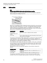
Contacts only for BUF8600 buffer modules with double-layer capacitors
Control contact ON and signaling contacts RDY and OK are only available for BUF8600
buffer modules with double-layer capacitors.
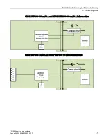
Buffer mode of the BUF8600 buffer module with double-layer capacitors can be prevented
using control contact ON (terminals "X1" and "X2"), if a scheduled shutdown of the power
supply is planned (e.g. for maintenance, period of no operation, end of work/shift). This
avoids unnecessarily discharging the buffer module. Deactivation via the control contact is
effective for all of the BUF8600 buffer modules in the system.
Control contact
Explanation
X1-X2 closed
(delivery state: via wire
jumper)
Buffer active, system is buffered when the power fails.
X1-X2 open
All of the buffer modules in the system deactivated; when the power
fails, the system is not buffered.
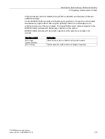
The signaling contact "Sufficient buffer readiness" RDY is in the form of a relay contact (NO
contact, terminals "13" and "14"), and signals that the buffer module is charged to x %
(factory setting: 85 %) and is therefore ready for buffering. The threshold value can be freely
parameterized via Industrial Ethernet / PROFINET interface.
For two BUF8600 buffer modules with double-layer capacitors in the system, the threshold
that is set refers to the sum of the charged energy storage devices in both buffer modules.
The signal "Sufficient buffer readiness" refers exclusively to the BUF8600 buffer modules
with double-layer capacitors in the system.
BUF8600 buffer modules with electrolytic capacitors in the system are not taken into
account.
Signaling contact
Explanation
13-14 open
(quiescent state)
Charge state of the buffer module or two buffer modules < x % - or
module fault
13-14 closed
Charge state of the buffer module or two buffer modules ≥ x %
The signaling contact "Buffer mode OK" is in the form of a relay contact (NO contact,
terminals "23" and "24") and signals that the system is in buffer mode. This means that
Содержание SITOP BUF8600
Страница 6: ...Overview PSU8600power supply systems 6 Manual 04 2016 A5E35883207 7 76 ...
Страница 12: ...Safety instructions PSU8600power supply systems 12 Manual 04 2016 A5E35883207 7 76 ...
Страница 164: ...Engineering and remote access 7 4 SIMATIC STEP 7 PSU8600power supply systems 164 Manual 04 2016 A5E35883207 7 76 ...
Страница 240: ...Technical data 9 9 Dimension drawings PSU8600power supply systems 240 Manual 04 2016 A5E35883207 7 76 ...
Страница 246: ...Environmental conditions PSU8600power supply systems 246 Manual 04 2016 A5E35883207 7 76 ...
Страница 250: ...Environment PSU8600power supply systems 250 Manual 04 2016 A5E35883207 7 76 ...

