Engineering and remote access
7.3 SIMATIC STEP 7 in the TIA Portal
PSU8600power supply systems
Manual, 04.2016, A5E35883207-7-76
137
●
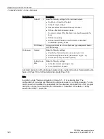
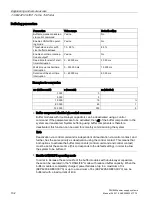
Setpoint output voltage
Define the required output voltage.
●
Response threshold of the output current
Define the required response threshold value of the output current for the particular
output.
●
Prewarning threshold output current
Using prewarning thresholds for the output current of the individual outputs, you can
identify at an early stage slight (creeping) changes in the current demand of the
connected load. This prewarning function facilitates the highest possible availability of the
system (maintenance function).
Enter a value of "0 %" to deactivate the prewarning threshold.
●
ON delay
In order to reduce the load on the overall SITOP PSU8600 power supply system as a
result of simultaneous switch-on current peaks of the loads at the various outputs, an on
delay between the outputs can be selected when switching on.
When the on delay is activated, the outputs are sequentially switched-on with a 25 ms or
100 ms delay time between the outputs, or load optimized.
When the variable on delay is activated, you can assign individual on delay times to the
individual outputs.
●
Mode
Two overload responses can be defined for all outputs:
–
In the ELECTRONIC SHUTDOWN mode, overload is permitted for a defined time.
The output is electronically shut down after the limit value has been exceeded (see
Overload shutdown and carrying out a reset (Page 56)).
–
In the CONSTANT CURRENT mode, an overload current is continually permissible
(U/I curve) according to a defined characteristic. The overload current is limited to a
maximum of 150 % of the setting value of the current potentiometer for a duration of 5
seconds (LED "ON/OFF/RST" flashes green with 2 Hz); the current is then limited to
100 % of the setting value (LED "ON/OFF/RST" flashes green with 1 Hz) as long as
there is an overload condition.
7.3.7
Loading the configuration (commissioning)
In the delivered state, the SITOP PSU8600 has not yet been assigned any IP address and
the DHCP protocol is deactivated.
When the SITOP PSU8600 is first connected with a controller (SIMATIC S7- control system),
it must be assigned a device name and an IP address by the controller. A new configuration
can be loaded to the device using STEP 7 in the TIA Portal.
Содержание SITOP BUF8600
Страница 6: ...Overview PSU8600power supply systems 6 Manual 04 2016 A5E35883207 7 76 ...
Страница 12: ...Safety instructions PSU8600power supply systems 12 Manual 04 2016 A5E35883207 7 76 ...
Страница 164: ...Engineering and remote access 7 4 SIMATIC STEP 7 PSU8600power supply systems 164 Manual 04 2016 A5E35883207 7 76 ...
Страница 240: ...Technical data 9 9 Dimension drawings PSU8600power supply systems 240 Manual 04 2016 A5E35883207 7 76 ...
Страница 246: ...Environmental conditions PSU8600power supply systems 246 Manual 04 2016 A5E35883207 7 76 ...
Страница 250: ...Environment PSU8600power supply systems 250 Manual 04 2016 A5E35883207 7 76 ...

