


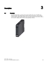


Description
3.4 Device versions
SIRIUS 3RM1 motor starter
30
Manual, 06/2016, A5E0345285095020A/RS-AE/005
Current ranges
The 3RM1 motor starters are designed for the following rated operational currents of the
loads:
Table 3- 2
Current ranges
Versions
Adjustable response value current
[A]
Maximum permissible motor power
at 400 V AC [kW]
3RM1.01-.....
0.1 ... 0.5
0.12
3RM1.02-.....
0.4 ... 2
0.75
3RM1.07-.....*
1.6 ... 7
3
* The versions of the 3RM1.07-..... motor starter are also suitable for operating resistive loads (e.g.
heaters) up to a rated operational current of I
AC51
= 10 A.
Control supply voltages
The 3RM1 motor starters are designed for the following control supply voltages:
Table 3- 3
Control supply voltages
Versions
Control supply voltage
3RM1...-.AA0.
24 V DC
3RM1...-.AA1.
110 … 230 V AC 50/60 Hz; 110 V DC
Note the following information for the different device versions:
Note
Motor starters with 24 V DC control supply voltage
As is usual on solid-state motor starters, a buffering capacitance of 250 µF is installed in the
24 V DC control circuit of the 3RM1 Standard and Failsafe motor starters. Its purpose is to
specifically shut down the motor with the semiconductors in the event of failure or
disconnection of the control supply voltage. As a result, charging currents can arise briefly
upon activation of the control supply voltage. The buffering capacitance is decoupled by a
diode. This means that there is no influence on the dark test of safety-related outputs.
You can find more information on the Internet
https://support.industry.siemens.com/cs/ww/en/view/91372998
Note
3RM10/3RM12 Standard motor starters with 24 V DC control supply voltage
The same voltage source (potential) must be used for the control supply voltage and the
control inputs.
The reference point for the control inputs is terminal A2.