


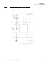


Typical circuits
A.2 Typical circuits for safety-related shutdown
SIRIUS 3RM1 motor starter
Manual, 06/2016, A5E0345285095020A/RS-AE/005
177
Note
Operational faults and malfunctions in communication
If the EMC Directive 2014/30/EC is not complied with when plants and devices are installed,
communication breaks may occur.
Note
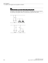
Cover the 3ZY12 device connector on the left-hand side using the cover supplied with the
device termination connector.
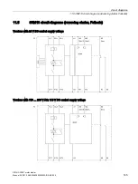
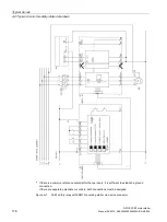
A.2.2
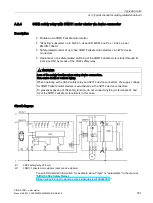
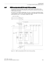
3SK1 safety relay with 3RM13 motor starter via device connector
The 3RM13 Failsafe motor starter is connected to a 3SK1 safety relay via a 3ZY1 device
connector.
The two directions of rotation are switched on and off operationally via IN1 and IN2, e.g. with
a PLC.
The control supply voltage (L+ and L-) to the motor starters is deactivated by the 3SK1
safety relay and the system is in a safe state.
Note
SILCL 3 in accordance with EN 62061/PL e in accordance with EN ISO 13849-1
A safety-related application up to SILCL 3 to EN 62061, PL e/Cat. 4 to EN ISO 13849-1 can
be realized in this way.
To achieve SILCL 3/PL e/Cat. 4 for the safety-related application, all components of the
safety functions (detecting/evaluating/reacting) must be designed accordingly.
WARNING
Loss of the safety function when using device connectors.
Can cause death or serious injury.
When operating with a 3SK1 safety relay and a device connector, the supply voltage for
3RM1 motor starters is established via the device connectors.
In this case, do not connect anything to terminals A1 and A2 of the 3RM1 motor starters, in
order to prevent bypassing of the safety function.