background image

Standard mapping 2-1

7SJ61...7SJ63, 7SJ65, 6MD63  PROFIBUS-DP – Bus mapping

C53000-L1840-B006-02

2-12

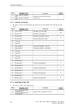
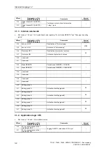
2.2.3 Fault 

locator


Ref. to chap. 1.5.8 for additional notes.

Offset

Designation of the

SIPROTEC objects

Comments

Scaling

(32767 corresponds to ...)

Internal

object no.

70

dist =

Fault locator:
Distance to fault (Fault location)

3276.7 km/miles

1119

2.2.4 Metered 

measurands


Ref. to chap. 1.3.3 for additional notes regarding scaling of metered measurands.

Offset

Designation of the

SIPROTEC objects

Comments

Scaling

(2

31

-1 of the unsigned long-

value corresponds to ...)

Internal

object no.

72

Wp(puls) =

Pulsed Energy Wp (active)
(metering impulses at binary input)

2

31

-1 impulses

888

76

Wq(puls) =

Pulsed Energy Wq (reactive)
(metering impulses at binary input)

2

31

-1 impulses

889

80

WpForward=

Wp Forward (

metered measurand

derived from measured value

)

2

31

- 1 impulses

924

84

WqForward=

Wq Forward (

metered measurand

derived from measured value 

)

2

31

-1 impulses

925

88

WpReverse =

Wp Reverse (

metered measurand

derived from measured value

)

2

31

-1 impulses

928

92

WqReverse =

Wq Reverse (

metered measurand

derived fom measured value

)

2

31

-1 impulses

929

96

Op.Hours=

Counter of operating hours of the
primary equipment

2

31

-1 hours

1020

Содержание SIPROTEC4 6MD63

Страница 1: ... with local control 6MD63 Communication module PROFIBUS DP Bus mapping Revision 2 1 Edition October 2001 C53000 L1840 B006 02 Preface Data in the PROFIBUS DP messages 1 Standard mapping 2 1 2 Standard mapping 2 2 3 Standard mapping 2 3 4 Standard mapping 2 4 5 Glossary Index Cover ...

Страница 2: ...hout prior notice Copyright ã Siemens AG 2001 All rights reserved Passing on or reproduction of this document utilization and revelation of its contents is not permitted without express permission Violations shall be cause for damage claims All rights reserved in particular when a patent is issued or a general model registered Registered trademarks SIPROTECâ und DIGSIâ are registered trademarks of...

Страница 3: ...SJ61 Function operation assembly and commissioning of the SIPROTEC device 7SJ61 C53000 G1140 C118 2 Multifunction protection with control SIPROTEC 7SJ62 Function operation assembly and commissioning of the SIPROTEC device 7SJ62 C53000 G1140 C121 2 Multifunction protection with control SIPROTEC 7SJ63 Function operation assembly and commissioning of the SIPROTEC device 7SJ63 C53000 G1140 C120 2 Mult...

Страница 4: ...dividual chapters you will find information in the left margin of each page which will give you an overview of the contents of that particular paragraph Following the last chapter of this manual you will find a glossary containing definitions of technical terms and abbreviations used in this manual At the end of this manual you will find a comprehensive index for fast access to the information you...

Страница 5: ...Standard mapping 2 3 corrected Standard mapping 2 4 added Chap Using device firmware version 4 3 or higher added Description of Error with a summary alarm extended Feb 22nd 2001 chap 1 4 chap 4 2 3 chap 2 1 3 3 1 3 2 1 Parameterization of the PROFIBUS DP master Order number of the output module for standard mapping 2 3 corrected Offsets of metered measurands in Standard mapping 2 3 corrected Inter...

Страница 6: ...Revision index 7SJ61 7SJ63 7SJ65 6MD63 PROFIBUS DP Bus mapping C53000 L1840 B006 02 iv ...

Страница 7: ... Changing the setting group 1 11 1 5 4 CFC Incoming annunciations 1 12 1 5 5 Error with a summary alarm 1 12 1 5 6 Alarm summary event 1 13 1 5 7 Stop data transmission 1 13 1 5 8 Fault locator Fault location 1 13 1 6 Using device firmware version 4 3 or higher 1 14 2 Standard mapping 2 1 2 1 2 1 Message in output direction 2 1 2 1 1 Double commands with checkback indication 2 1 2 1 2 Single comma...

Страница 8: ... Recorded measured values 2 11 2 2 2 2 Measured values mean values 2 11 2 2 3 Fault locator 2 12 2 2 4 Metered measurands 2 12 3 Standard mapping 2 2 3 1 3 1 Message in output direction 3 1 3 1 1 Double commands with checkback indication 3 1 3 1 2 Single commands without checkback indication 3 1 3 1 3 Internal commands 3 2 3 1 4 Application logic CFC 3 2 3 2 Message in input direction 3 4 3 2 1 An...

Страница 9: ...signals 4 4 4 2 1 2 Single commands status 4 4 4 2 1 3 Input channels with allocation to the binary inputs and tagging 4 5 4 2 1 4 Application logic CFC 4 5 4 2 1 5 Diagnosis 4 6 4 2 1 6 Measurement supervision 4 6 4 2 1 7 Set point alarms 4 6 4 2 1 8 Status annunciations 4 7 4 2 2 Measured values 4 8 4 2 2 1 Recorded measured values 4 8 4 2 2 2 Measured values mean values 4 8 4 2 3 Metered measur...

Страница 10: ...000 L1840 B006 02 viii 5 2 1 5 Sensitive ground fault protection 5 14 5 2 1 6 Thermal overload protection 5 14 5 2 1 7 Directional time overcurrent protection 5 14 5 2 1 8 Diagnosis 5 14 5 2 2 Measured values 5 15 5 2 3 Metered measurands 5 15 6 Glossary 6 1 7 Index 7 1 ...

Страница 11: ...C device 7SJ61 7SJ63 7SJ65 6MD63 with the PROFIBUS DP master The listed SIPROTEC objects in the PROFIBUS DP message data area are sorted after byte offset beginning with 0 Variables with data type greater than or equal to 1 byte The offset defines the start of the most significant byte in the message e g Offset Designation of the SIPROTEC objects Comments Scaling 32767 corresponds to Internal obje...

Страница 12: ...0 Q0 ON OFF OFF 0 1 Q0 ON OFF ON Circuit breaker 17 4 Fail Ph Seq 1 Failure Phase Sequence 171 The checkback signal from the circuit breaker as double point indi cation is located in data byte 0 bit positions 2 0 bit 0 and 2 1 bit 1 The single point indication Fail Ph Seq is located in byte 17 bit position 2 4 The definitions of data types single point indication double point indication measured v...

Страница 13: ...ice composition there may be less than indicated output relays and corresponding PROFIBUS DP message positions available in the SIPROTEC device 1 3 Messages in input direction SIPROTEC device to the PROFIBUS DP master The messages in PROFIBUS DP input direction ref to chap 2 2 3 2 4 2 and 5 2 allow polling of switching devices status and binary inputs transmission of annunciations measurands and m...

Страница 14: ...uipment parameter address 1102 è 10 1000 A Product of Voltage transducer Primary voltage parameter address 0202 and Ratio factor Vph Vdelta parameter address 0206 è 1 0 10 32 kV Product of Current transducer Rated primary current parameter address 0204 and Ratio factor IN Iph parameter address 0207 or dependent on the device type Ratio factor INs Iph parameter address 0208 è 0 0 1000 A Power value...

Страница 15: ...1 Inom NOMINAL OPERATING CURRENT OF PRIMARY EQUIPMENT parameter address 1102 Example In the parameter set is configured Inom 100 A und Vnom 12 00 kV 60000 impulses correspond so that 1 h 100 A 12 kV 3 2078 46 kWh Note The type of the update cyclic with or without deletion and the update interval must be programmed for the metered measurands except for the operating hours meter with the parameteriz...

Страница 16: ...dications 146 single point indications 25 measured values integer 6 metered measureands unsigned long Fault locator Fault location integer Counter of operating hours unsigned long Standard mapping 2 2 The standard mapping 2 2 contains Output direction 7 double point commands 29 single point commands Input direction 7 double point indications 114 single point indications 10 measured values integer ...

Страница 17: ...tandard mapping 2 4 1FH 1BH 21H 28 bytes input and 2 bytes output direction PROFIBUS DP master At the configuration of a PROFIBUS DP slave of the SIPROTEC devices in the parameterization system of the PROFIBUS DP masters are to select the following modules for the 7SJ61 7SJ63 7SJ65 6MD63 standard mappings and to allocate associated addresses in the I O addressing range of the PROFIBUS DP master St...

Страница 18: ...TEC device in output direction ref to chap 2 1 3 1 4 1 and 5 1 Note There is dependently on the PROFIBUS DP master in addition possibly the demand to put the base address of the inputs on a value divisible by four so that accesses on the metered measurands unsigned long values ref to chap 2 2 4 3 2 3 4 2 3 and 5 2 3 can be correctly carried out in the PROFIBUS DP master Compatibility to DIGSI 4 1 ...

Страница 19: ...mation in the following manuals Manual Contents Order number PROFIBUS DP Bus mapping 7SJ61 Data in the PROFIBUS DP messages of the SIPROTEC device 7SJ61 C53000 L1840 B002 01 PROFIBUS DP Busmapping 7SJ62 63 Data in the PROFIBUS DP messages of the SIPROTEC devices 7SJ62 63 C53000 L1840 B003 01 PROFIBUS DP Bus mapping 6MD63 Data in the PROFIBUS DP messages of the SIPROTEC device 6MD63 C53000 L1840 B0...

Страница 20: ...DP Communication profile ref to page i If a mapping file is assigned to a SIPROTEC device and if the data size of the PROFIBUS DP message of this SIPROTEC device is changed by choice of a new mapping file then assignments which are not available in the existing mapping file remain unassigned furthermore 1 5 1 Single commands The command output mode pulse output continuous output is changeable for ...

Страница 21: ...IBUS DP input message In this case the status of Control mode REMOTE in output direction has to be updated by the PROFIBUS DP master References Standard mapping 2 1 ref to chap 2 1 3 Standard mapping 2 2 ref to chap 3 1 3 Standard mapping 2 3 ref to chap 4 1 3 Standard mapping 2 4 not pre allocated 1 5 3 Changing the setting group In order to change the setting group the value 10 ON must be transm...

Страница 22: ...g 2 4 ref to chap 5 1 4 1 5 5 Error with a summary alarm The Error with a summary alarm is ON if at least one of the following internal alarms assumes the value ON Depending on the device composition not all alarms are available 7SJ61 7SJ62 The Error with a summary alarm corresponds to the internal alarm I O Board error Additionally with firmware version 4 3 or higher Error Board 1 Error 5V Error ...

Страница 23: ... not supported via PROFIBUS DP communication If Stop data transmission is active nevertheless data via PROFIBUS DP will be transmitted furthermore The annunciation DataStop signals the activation of Stop data transmission however and can be evaluated correspondingly in the PROFIBUS DP master References Standard mapping 2 1 ref to chap 2 2 1 21 Standard mapping 2 2 ref to chap 3 2 1 18 Standard map...

Страница 24: ...ing annunciation 16 UsCfcSpI16 CFC Output indication 1 UsCfcSpO1 CFC Output indication 16 UsCfcSpO16 Input channels with allocation to the binary inputs and tagging Input channel 1 UsrSpO C1 Input channel 8 UsrSpO C32 After creating a SIPROTEC device with device firmware version 4 3 or higher in the parametrization system DIGSI and assignment of a PROFIBUS DP mapping the PROFIBUS DP message positi...

Страница 25: ... relays 1 pole 0 6 Q2 ON OFF OFF 0 7 Q2 ON OFF ON Impulse output 2 relays 1 pole 1 0 Q9 ON OFF OFF 1 1 Q9 ON OFF ON Impulse output 2 relays 1 pole 1 2 Switching device D1 UsrDC1 OFF 1 3 Switching device D1 UsrDC1 ON Impulse output 4 relays 2 pole 1 4 Switching device D2 UsrDC2 OFF 1 4 Switching device D2 UsrDC2 ON Impulse output 2 relays 1 pole 2 1 2 Single commands without checkback indication Re...

Страница 26: ...ation of protection functions 2 7 Protection ON Activation of potection functions 52 3 0 reserved 3 1 reserved 3 2 Mode REMOTE Control mode REMOTE LOCKED 3 3 Mode REMOTE Control mode REMOTE UNLOCKED 3 4 reserved 3 5 reserved 3 6 reserved 3 7 reserved 4 0 Setting group A 4 1 Setting group A Activation of setting group A 53 4 2 Setting group B 4 3 Setting group B Activation of setting group B 54 4 4...

Страница 27: ...ciation 8 UsCfcSpI8 OFF 6 7 CFC Incoming annunciation 8 UsCfcSpI8 ON Tagging ON OFF released as CFC input 7 0 CFC Incoming annunciation 9 UsCfcSpI9 OFF 7 1 CFC Incoming annunciation 9 UsCfcSpI9 ON Tagging ON OFF released as CFC input 7 2 CFC Incoming annunciation 10 UsCfcSpI10 OFF 7 3 CFC Incoming annunciation 10 UsCfcSpI10 ON Tagging ON OFF released as CFC input 7 4 CFC Incoming annunciation 11 U...

Страница 28: ...FF 1 3 Switching device D1 UsrDC1 ON Double point indication ON OFF 1 4 Switching device D2 UsrDC2 OFF 1 5 Switching device D2 UsrDC2 ON Double point indication ON OFF 2 2 1 2 Single commands status Ref to chap 1 6 for additional notes Offset Designation of the SIPROTEC objects Comments Internal object no 1 6 Output channel E1 UsrSC5 Single point indication ON OFF 1 7 Output channel E2 UsrSC6 Sing...

Страница 29: ...eased as CFC output 3 7 CFC Output indication 8 UsCfcSpO8 Single point indication ON OFF released as CFC output 4 0 CFC Output indication 9 UsCfcSpO9 Single point indication ON OFF released as CFC output 4 1 CFC Output indication 10 UsCfcSpO10 Single point indication ON OFF released as CFC output 4 2 CFC Output indication 11 UsCfcSpO11 Single point indication ON OFF released as CFC output 4 3 CFC ...

Страница 30: ...nd Fault 1 AR TRIP ground fault 2869 6 7 TRIP Ph Fault 1 AR TRIP phase fault 2870 2 2 1 7 Time overcurrent protection Offset Designation of the SIPROTEC objects Comments Internal object no 7 0 50 51 PH OFF 1 Time overcurrent phase is OFF 1751 7 1 50N 51N OFF 1 Time overcurrent ground is OFF 1756 7 2 50 N 51 N PU 1 Time overcurrent PICKUP 1761 7 3 50 51 Ph A PU 1 Time overcurrent phase A picked up ...

Страница 31: ...3 67 1 TRIP 1 67 1 TRIP 2665 10 4 67 TOC TRIP 1 67 TOC TRIP 2675 10 5 67N 2 TRIP 1 67N 2 TRIP 2679 10 6 67N 1 TRIP 1 67N 1 TRIP 2683 10 7 67N TOC TRIP 1 67N TOC TRIP 2686 11 0 67 A picked up 1 Directional time overcurrent Phase A picked up 2692 11 1 67 B picked up 1 Directional time overcurrent Phase B picked up 2693 11 2 67 C picked up 1 Directional time overcurrent Phase C picked up 2694 11 3 67...

Страница 32: ...tection is switched OFF 1211 13 2 64 Pickup 1 64 displacement voltage pick up 1215 13 3 64 TRIP 1 64 displacement voltage element TRIP 1217 13 4 50Ns 2 TRIP 1 50Ns 2 TRIP 1223 13 5 50Ns 1 TRIP 1 50Ns 1 TRIP 1226 13 6 51Ns TRIP 1 51Ns TRIP 1229 13 7 Sens Gnd Pickup 1 Sensitive ground fault pick up 1271 14 0 Sens Gnd Ph A 1 Sensitive ground fault picked up in phase A 1272 14 1 Sens Gnd Ph B 1 Sensit...

Страница 33: ...823 15 7 66 OFF 1 Motor start protection is switched OFF 4824 16 0 66 TRIP 1 Motor start protection TRIP 4827 2 2 1 16 Startup supervision Offset Designation of the SIPROTEC objects Comments Internal object no 16 1 START SUP OFF 1 Startup supervision is switched OFF 6811 16 2 START SUP OFF 1 Startup supervision TRIP 6821 16 3 Rotor locked 1 Rotor locked 6822 16 4 START SUP pu 1 Startup supervision...

Страница 34: ...76 18 3 SP Pdmd 1 Set point Pdmd 277 18 4 SP Qdmd 1 Set point Qdmd 278 18 5 SP Sdmd 1 Set point Sdmd 279 18 6 SP 37 1 alarm 1 Set point 37 1 undercurrent alarm 284 18 7 SP PF 55 alarm 1 Set point 55 power factor alarm 285 2 2 1 21 Status annunciations Ref to chap 1 5 7 for additional notes regarding Stop data transmission Offset Designation of the SIPROTEC objects Comments Internal object no 19 0 ...

Страница 35: ...42 40 S S apparent power 32 767 MVAR 645 42 Freq Frequency 327 67 Hz 644 44 INs Real Resistive ground current in isol systems 3276 7 A 701 46 INs Reac Reactive ground current in isol systems 3276 7 A 702 48 PF Power Factor 3 2767 901 50 I1 I1 positive sequence 3276 7 A 605 52 I2 I2 negative sequence 3276 7 A 606 54 V1 V1 positive sequence 32 767 kV 629 56 V2 V2 negative sequence 32 767 kV 630 58 T...

Страница 36: ...Scaling 231 1 of the unsigned long value corresponds to Internal object no 72 Wp puls Pulsed Energy Wp active metering impulses at binary input 231 1 impulses 888 76 Wq puls Pulsed Energy Wq reactive metering impulses at binary input 231 1 impulses 889 80 WpForward Wp Forward metered measurand derived from measured value 231 1 impulses 924 84 WqForward Wq Forward metered measurand derived from mea...

Страница 37: ... relays 1 pole 0 6 Q2 ON OFF OFF 0 7 Q2 ON OFF ON Impulse output 2 relays 1 pole 1 0 Q9 ON OFF OFF 1 1 Q9 ON OFF ON Impulse output 2 relays 1 pole 1 2 Switching device D1 UsrDC1 OFF 1 3 Switching device D1 UsrDC1 ON Impulse output 4 relays 2 pole 1 4 Switching device D2 UsrDC2 OFF 1 5 Switching device D2 UsrDC2 ON Impulse output 2 relays 1 pole 3 1 2 Single commands without checkback indication Re...

Страница 38: ...ation of protection functions 2 7 Protection ON Activation of potection functions 52 3 0 reserved 3 1 reserved 3 2 Mode REMOTE Control mode REMOTE LOCKED 3 3 Mode REMOTE Control mode REMOTE UNLOCKED 3 4 reserved 3 5 reserved 3 6 reserved 3 7 reserved 4 0 Setting group A 4 1 Setting group A Activation of setting group A 53 4 2 Setting group B 4 3 Setting group B Activation of setting group B 54 4 4...

Страница 39: ...ciation 8 UsCfcSpI8 OFF 6 7 CFC Incoming annunciation 8 UsCfcSpI8 ON Tagging ON OFF released as CFC input 7 0 CFC Incoming annunciation 9 UsCfcSpI9 OFF 7 1 CFC Incoming annunciation 9 UsCfcSpI9 ON Tagging ON OFF released as CFC input 7 2 CFC Incoming annunciation 10 UsCfcSpI10 OFF 7 3 CFC Incoming annunciation 10 UsCfcSpI10 ON Tagging ON OFF released as CFC input 7 4 CFC Incoming annunciation 11 U...

Страница 40: ... 2 Switching device D1 UsrDC1 OFF 1 3 Switching device D1 UsrDC1 ON Double point indication ON OFF 1 4 Switching device D2 UsrDC2 OFF 1 5 Switching device D2 UsrDC2 ON Double point indication ON OFF 3 2 1 2 Single commands status Ref to chap 1 6 for additional notes Offset Designation of the SIPROTEC objects Comments Internal object no 1 6 Output channel E1 UsrSC5 Single point indication ON OFF 1 ...

Страница 41: ...dication 7 UsCfcSpO7 Single point indication ON OFF released as CFC output 3 7 CFC Output indication 8 UsCfcSpO8 Single point indication ON OFF released as CFC output 4 0 CFC Output indication 9 UsCfcSpO9 Single point indication ON OFF released as CFC output 4 1 CFC Output indication 10 UsCfcSpO10 Single point indication ON OFF released as CFC output 4 2 CFC Output indication 11 UsCfcSpO11 Single ...

Страница 42: ...2863 6 6 TRIP Gnd Fault 1 AR TRIP ground fault 2869 6 7 TRIP Ph Fault 1 AR TRIP phase fault 2870 3 2 1 7 Time overcurrent protection Offset Designation of the SIPROTEC objects Comments Internal object no 7 0 50 51 PH OFF 1 Time overcurrent phase is OFF 1751 7 1 50N 51N OFF 1 Time overcurrent ground is OFF 1756 7 2 50 N 51 N PU 1 Time overcurrent PICKUP 1761 7 3 50 51 Ph A PU 1 Time overcurrent pha...

Страница 43: ...ed OFF 1451 9 7 50BF TRIP 1 Circuit breaker failure TRIP 1471 3 2 1 11 Thermal overload protection Offset Designation of the SIPROTEC objects Comments Internal object no 10 0 49 O L OFF 1 Thermal overload protection is switched OFF 1511 10 1 49 O L I Alarm 1 49 Overload current alarm I alarm 1515 10 2 49 O L Theta Alarm 1 49 Overload alarm Near thermal TRIP 1516 10 3 49 Windings O L 1 49 Winding o...

Страница 44: ...e ACTIVE 1997 3 2 1 16 Measurement supervision Offset Designation of the SIPROTEC objects Comments Internal object no 12 1 Fail I Superv 1 Failure General current supervision 161 12 2 Failure Sum I 1 Failure Current summation 162 12 3 Fail Ph Seq 1 Failure Phase sequence 171 12 4 MeasSup OFF 1 Measurement supervision is switched OFF 197 3 2 1 17 Set point alarms Offset Designation of the SIPROTEC ...

Страница 45: ...14 0 No Volt 1 Binary input No voltage fuse blown is active 14 1 DataStop 1 Stop data transmssion is active 14 2 Test mode 1 Test mode is active 14 3 Cntrl Auth 7SJ61 7SJ82 Control authority 0 REMOTE 1 LOCAL 14 4 ModeLOCAL 7SJ61 7SJ82 Control mode LOCAL 0 LOCKED 1 UNLOCKED 14 5 ModeREMOTE Control mode REMOTE 0 LOCKED 1 UNLOCKED 14 6 reserved 14 7 reserved 15 0 reserved 15 1 reserved 15 2 reserved ...

Страница 46: ...05 30 Theta Stator Temperature of stator 327 67 806 3 2 2 2 Measured values mean values Offset Designation of the SIPROTEC objects Comments Scaling 32767 corresponds to Internal object no 32 I1 dmd I1 positive sequence demand 3276 7 A 833 34 reserved 3 2 3 Metered measurands Ref to chap 1 3 3 for additional notes regarding scaling of metered measurands Offset Designation of the SIPROTEC objects Co...

Страница 47: ...elays 1 pole 0 6 Q2 ON OFF OFF 0 7 Q2 ON OFF ON Impulse output 2 relays 1 pole 1 0 Q9 ON OFF OFF 1 1 Q9 ON OFF ON Impulse output 2 relays 1 pole 1 2 Switching device D1 UsrDC1 OFF 1 3 Switching device D1 UsrDC1 ON Impulse output 4 relays 2 pole 1 4 Switching device D2 UsrDC2 OFF 1 5 Switching device D2 UsrDC2 ON Impulse output 2 relays 1 pole 1 6 Switching device D3 UsrDC3 OFF 1 7 Switching device...

Страница 48: ...e REMOTE Offset Designation of the SIPROTEC objects Comments Internal object no 3 4 reserved 3 5 reserved 3 6 Mode REMOTE Control mode REMOTE LOCKED 3 7 Mode REMOTE Control mode REMOTE UNLOCKED 4 1 4 Application logic CFC Ref to chap 1 5 4 and 1 6 for additional notes Offset Designation of the SIPROTEC objects Comments Internal object no 4 0 CFC Incoming annunciation 1 UsCfcSpI1 OFF 4 1 CFC Incomi...

Страница 49: ...ciation 10 UsCfcSpI10 OFF 6 3 CFC Incoming annunciation 10 UsCfcSpI10 ON Tagging ON OFF released as CFC input 6 4 CFC Incoming annunciation 11 UsCfcSpI11 OFF 6 5 CFC Incoming annunciation 11 UsCfcSpI11 ON Tagging ON OFF released as CFC input 6 6 CFC Incoming annunciation 12 UsCfcSpI12 OFF 6 7 CFC Incoming annunciation 12 UsCfcSpI12 ON Tagging ON OFF released as CFC input 7 0 CFC Incoming annunciat...

Страница 50: ... 2 Switching device D1 UsrDC1 OFF 1 3 Switching device D1 UsrDC1 ON Double point indication ON OFF 1 4 Switching device D2 UsrDC2 OFF 1 5 Switching device D2 UsrDC2 ON Double point indication ON OFF 1 6 Switching device D3 UsrDC3 OFF 1 7 Switching device D3 UsrDC3 ON Double point indication ON OFF 4 2 1 2 Single commands status Ref to chap 1 6 for additional notes Offset Designation of the SIPROTE...

Страница 51: ... output 4 2 CFC Output indication 3 UsCfcSpO3 Single point indication ON OFF released as CFC output 4 3 CFC Output indication 4 UsCfcSpO4 Single point indication ON OFF released as CFC output 4 4 CFC Output indication 5 UsCfcSpO5 Single point indication ON OFF released as CFC output 4 5 CFC Output indication 6 UsCfcSpO6 Single point indication ON OFF released as CFC output 4 6 CFC Output indicatio...

Страница 52: ...ffset Designation of the SIPROTEC objects Comments Internal object no 7 0 Fail I Superv 1 Failure General current supervision 161 7 1 Failure Sum I 1 Failure Current summation 162 7 2 Fail Ph Seq 1 Failure Phase sequence 171 7 3 MeasSup OFF 1 Measurement supervision is switched OFF 197 4 2 1 7 Set point alarms Offset Designation of the SIPROTEC objects Comments Internal object no 7 4 SP Op Hours 1...

Страница 53: ... of the SIPROTEC objects Comments Internal object no 9 0 No Volt 1 Binary input No voltage fuse blown is active 9 1 DataStop 1 Stop data transmssion is active 9 2 Test mode 1 Test mode is active 9 3 Cntrl Auth 7SJ63 7SJ65 6MD63 Control authority 0 REMOTE 1 LOCAL 9 4 ModeLOCAL 7SJ63 7SJ65 6MD63 Control mode LOCAL 0 LOCKED 1 UNLOCKED 9 5 ModeREMOTE Control mode REMOTE 0 LOCKED 1 UNLOCKED 9 6 reserve...

Страница 54: ...a Vc a 32 767 kV 626 24 VN VN 32 767 kV 627 26 P P active power 32 767 MW 641 28 Q Q reactive power 32 767 MVAR 642 30 S S apparent power 32 767 MVAR 645 32 Freq Frequency 327 67 Hz 644 34 PF Power Factor 3 2767 901 36 I1 I1 positive sequence 3276 7 A 605 38 I2 I2 negative sequence 3276 7 A 606 40 V1 V1 positive sequence 32 767 kV 629 42 V2 V2 negative sequence 32 767 kV 630 44 Td1 Transducer 1 32...

Страница 55: ... impulses at binary input 231 1 impulses 888 56 Wq puls Pulsed Energy Wq reactive metering impulses at binary input 231 1 impulses 889 60 WpForward Wp Forward metered measurand derived from measured value 231 1 impulses 924 64 WqForward Wq Forward metered measurand derived from measured value 231 1 impulses 925 68 WpReverse Wp Reverse metered measurand derived from measured value 231 1 impulses 92...

Страница 56: ...Standard mapping 2 3 7SJ61 7SJ63 7SJ65 6MD63 PROFIBUS DP Bus mapping C53000 L1840 B006 02 4 10 ...

Страница 57: ...OFF 0 5 Q8 ON OFF ON Impulse output 2 relays 1 pole 5 1 2 Single commands without checkback indication Ref to chap 1 5 1 and 1 6 for additional notes Offset Designation of the SIPROTEC objects Comments Internal object no 0 6 Output channel E1 UsrSC5 OFF 0 7 Output channel E1 UsrSC5 ON Impulse output 1 relay 1 pole 5 1 3 Internal commands Ref to chap 1 5 3 for additional notes regarding Changing th...

Страница 58: ...6 for additional notes Offset Designation of the SIPROTEC objects Comments Internal object no 1 4 CFC Incoming annunciation 1 UsCfcSpI1 OFF 1 5 CFC Incoming annunciation 1 UsCfcSpI1 ON Tagging ON OFF released as CFC input 1 6 CFC Incoming annunciation 2 UsCfcSpI2 OFF 1 7 CFC Incoming annunciation 2 UsCfcSpI2 ON Tagging ON OFF released as CFC input ...

Страница 59: ...0 7 CFC Output indication 1 UsCfcSpO1 Single point indication ON OFF released as CFC output 1 0 CFC Output indication 2 UsCfcSpO2 Single point indication ON OFF released as CFC output 1 1 CFC Output indication 3 UsCfcSpO3 Single point indication ON OFF released as CFC output 1 2 CFC Output indication 4 UsCfcSpO4 Single point indication ON OFF released as CFC output 1 3 CFC Output indication 5 UsCf...

Страница 60: ... Comments Internal object no 2 6 67 2 TRIP 1 67 2 TRIP 2649 2 7 67 1 TRIP 1 67 1 TRIP 2665 5 2 1 8 Diagnosis Ref to chap 1 5 5 and 1 5 6 for additional notes regarding Error with a summary alarm and Alarm summary event Offset Designation of the SIPROTEC objects Comments Internal object no 3 0 Device OK 1 Update of the device replica in the SIPROTEC device completed after initial start or restart 5...

Страница 61: ... 603 12 INs Reac Reactive ground current in isol systems 3276 7 A 702 14 P P active power 32 767 MW 641 16 Q Q reactive power 32 767 MVAR 642 18 PF Power Factor 3 2767 901 5 2 3 Metered measurands Ref to chap 1 3 3 for additional notes regarding scaling of metered measurands Offset Designation of the SIPROTEC objects Comments Scaling 231 1 of the unsigned long value corresponds to Internal object ...

Страница 62: ...Standard mapping 2 4 7SJ61 7SJ63 7SJ65 6MD63 PROFIBUS DP Bus mapping C53000 L1840 B006 02 5 16 ...

Страница 63: ...ion Input data input direction Data from the PROFIBUS DP slave to the PROFIBUS DP master Mapping Allocation of the SIPROTEC data objects to the positions in the PROFIBUS DP messages Octet Term from EN 50170 one octet corresponds to 8 bits OLM Optical Link Module Output data output direction Data from the PROFIBUS DP master to the PROFIBUS DP slave PNO PROFIBUS Nutzerorganisation PROFIBUS DP PROFIB...

Страница 64: ...Glossary 7SJ61 7SJ63 7SJ65 6MD63 PROFIBUS DP Bus mapping C53000 L1840 B006 02 6 2 ...

Страница 65: ... REMOTE 1 11 D definitions of data types 1 2 Double commands 3 1 Directional time overcurrent protection 2 7 Double point indication 2 4 3 4 4 4 E Error with a summary alarm 1 12 F Fault locator 2 12 Frequency protection 2 7 M Measured values 1 4 2 11 3 10 4 8 5 15 Measurement supervision 2 10 Metered measurands 1 5 2 12 3 10 4 9 Motor start protection 2 9 3 7 O operating hours meter 1 5 output re...

Страница 66: ...Index 7SJ61 7SJ63 7SJ65 6MD63 PROFIBUS DP Bus mapping C53000 L1840 B006 02 7 2 ...

Отзывы: