


4 Technical Data
442
7UT613/63x Manual
C53000-G1176-C160-2
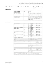
4.4
Time Overcurrent Protection for Phase and Residual Currents
Characteristics
Current Stages
Definite-time stages
DT
I
Ph
>>, 3
I
0
>>,
I
Ph
>, 3
I
0
>
Inverse time stages
(acc. to IEC or ANSI)
IT
I
P
, 3
I
0P
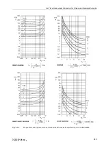
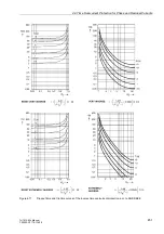
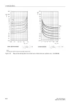
one of the tripping curves depicted in figures
to 4-12 on the right-hand side may be select-
ed;
alternatively user specified trip and reset char-
acteristic
Reset characteristics
(with disk emulation)
IT
For illustrations of possible reset time charac-
teristics see figures to 4-12 on the left-hand
side.
High current stages
I
Ph
>>
0.10 A to 35.00 A
1)
or
∞
(ineffective)
Steps 0.01 A
T
I
Ph>>
0.00 s to 60.00 s
or
∞
(no trip)
Steps 0.01 s
3
I
0
>>
0.10 A to 35.00 A
1)
or
∞
(ineffective)
Steps 0.01 A
T
3
I
0>>
0.00 s to 60.00 s
or
∞
(no trip)
Steps 0.01 s
Definite time current elements
(50Ns-2, 50Ns-1)
I
Ph
>
0.10 A to 35.00 A
1)
or
∞
(ineffective)
Steps 0.01 A
T
I
Ph>
0.00 s to 60.00 s
or
∞
(no trip)
Steps 0.01 s
3
I
0
>
0.10 A to 35.00 A
1)
or
∞
(ineffective)
Steps 0.01 A
T
3
I
0>
0.00 s to 60.00 s
or
∞
(no trip)
Steps 0.01 s
Inverse current elements (51Ns-
IEC)
I
P
0.10 A to 4.00 A
1)
Steps 0.01 A
T
I
P
0.05 s to 3.20 s
or
∞
(no trip)
Steps 0.01 s
3
I
0P
0.05 A to 4.00 A
1)
Steps 0.01 A
T
3
I
0P
0.05 s to 3.20 s
or
∞
(no trip)
Steps 0.01 s
Inverse current elements (51Ns-
ANSI)
I
P
0.10 A to 4.00 A
1)
Steps 0.01 A
D
I
P
0.50 s to 15.00 s
or
∞
(no trip)
Steps 0.01 s
3
I
0P
0.05 A to 4.00 A
1)
Steps 0.01 A
D
3
I
0P
0.50 s to 15.00 s
or
∞
(no trip)
Steps 0.01 s
Tolerances with inverse time
2)
currents
3 % of set value or 1 % rated current
times
1 % of set value or 10 ms
Tolerances with definite time (IEC)
2)
currents
Pickup at
1.05
≤
I
/
I
P
≤
1.15;
or 1.05
≤
I
/3
I
0P
≤
1.15
Содержание SIPROTEC 7UT613 series
Страница 16: ...Contents 16 7UT613 63x Manual C53000 G1176 C160 2 Literature 631 Glossary 623 Index 633 ...
Страница 30: ...1 Introduction 30 7UT613 63x Manual C53000 G1176 C160 2 ...
Страница 506: ...A Appendix 506 7UT613 63x Manual C53000 G1176 C160 2 7UT633 D E ...
Страница 508: ...A Appendix 508 7UT613 63x Manual C53000 G1176 C160 2 7UT633 P Q ...
Страница 510: ...A Appendix 510 7UT613 63x Manual C53000 G1176 C160 2 7UT635 D E ...
Страница 512: ...A Appendix 512 7UT613 63x Manual C53000 G1176 C160 2 7UT635 P Q ...
Страница 515: ...A 2 Terminal Assignments 515 7UT613 63x Manual C53000 G1176 C160 2 7UT633 B ...
Страница 516: ...A Appendix 516 7UT613 63x Manual C53000 G1176 C160 2 7UT633 B Figure A 7 General diagram 7UT633 panel surface mounting ...
Страница 517: ...A 2 Terminal Assignments 517 7UT613 63x Manual C53000 G1176 C160 2 7UT633 N ...
Страница 518: ...A Appendix 518 7UT613 63x Manual C53000 G1176 C160 2 7UT633 N Figure A 8 General diagram 7UT633 panel surface mounting ...
Страница 519: ...A 2 Terminal Assignments 519 7UT613 63x Manual C53000 G1176 C160 2 7UT635 B ...
Страница 520: ...A Appendix 520 7UT613 63x Manual C53000 G1176 C160 2 7UT635 B Figure A 9 General diagram 7UT635 panel surface mounting ...
Страница 521: ...A 2 Terminal Assignments 521 7UT613 63x Manual C53000 G1176 C160 2 7UT635 N ...
Страница 522: ...A Appendix 522 7UT613 63x Manual C53000 G1176 C160 2 7UT635 N Figure A 10 General diagram 7UT635 panel surface mounting ...
Страница 622: ...A Appendix 622 7UT613 63x Manual C53000 G1176 C160 2 ...
Страница 632: ...Literature 632 7UT613 63x Manual C53000 G1176 C160 2 ...


