


2.20 Protection Function Control
295
7UT613/63x Manual
C53000-G1176-C160-2
2.20.2 Tripping Logic for the Entire Device
2.20.2.1 General Tripping
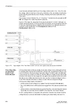
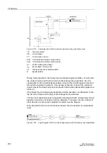
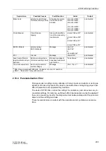
All tripping signals of the protection functions are OR–combined and lead to the alarm
„Relay TRIP“. This can be allocated to an LED or output relay as can be each of the
individual trip commands. It is suitable as general trip information as well as used for
the output of trip commands to the circuit breaker.
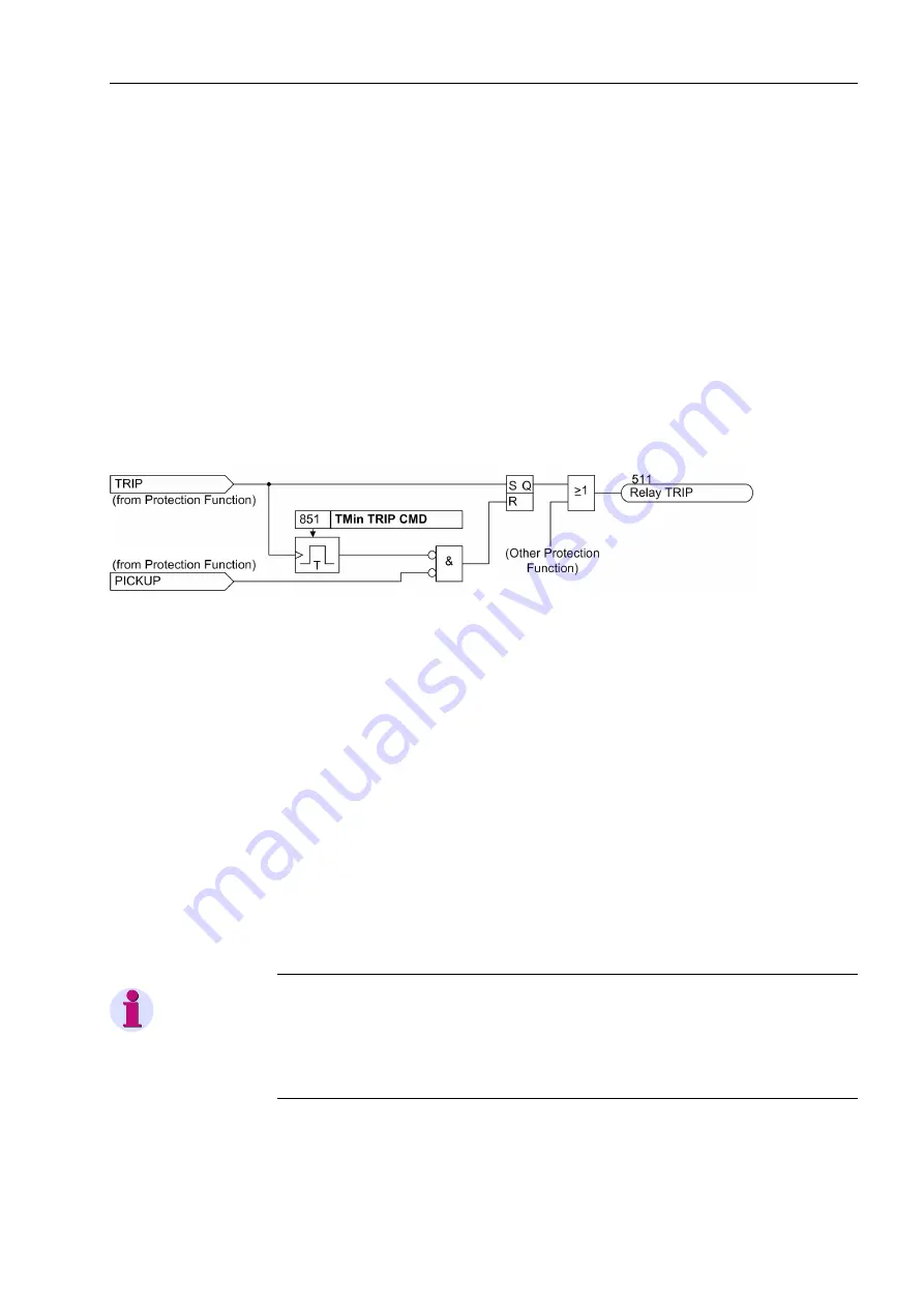
Once a trip command is activated, it is stored separately for each protection function.
At the same time a minimum trip command duration
TMin TRIP CMD
is started to
ensure that the command is sent to the circuit breaker long enough if the tripping pro-
tection function should drop off too quickly or if the breaker of the feeding end operates
faster. The trip commands cannot be terminated until the last protection function has
dropped off (no function activated) AND the minimum trip command duration is over.
Figure 2-121
Storage and termination of the trip command (simplified)
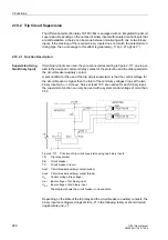
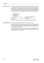
Reclosure Inter-
locking
After tripping the circuit breaker by a protection function the manual reclosure must
often be blocked until the cause for the protection operation is found.
Using the user-configurable logic functions (CFC) an automatic reclosure interlocking
function can be created. The default setting of 7UT613/63x offers a pre-defined CFC
logic which stores the trip command of the device until the command is acknowledged
manually. The CFC block is illustrated in the Appendix under „Preset CFC Charts“.
The internal output
„G-TRP Quit“
must be additionally assigned to the tripping
output relays which are to be sealed.
Acknowledgement is done via binary input
„>QuitG-TRP“
. With default configura-
tion, press function key F4 at the device front to acknowledge the stored trip com-
mand.
If the reclosure interlocking function is not required, delete the allocation between the
internal single-point indication
„G-TRP Quit“
and the source
„CFC“
in the configu-
ration matrix.
Note
The internal single-point indication
„G-TRP Quit“
is not affected by the setting
option
Block relay
of the protection functions. If this indication is allocated to a trip
relay, this relay will be actuated in case of a trip of the protection functions, even if
Block relay
is set for that function.
Содержание SIPROTEC 7UT613 series
Страница 16: ...Contents 16 7UT613 63x Manual C53000 G1176 C160 2 Literature 631 Glossary 623 Index 633 ...
Страница 30: ...1 Introduction 30 7UT613 63x Manual C53000 G1176 C160 2 ...
Страница 506: ...A Appendix 506 7UT613 63x Manual C53000 G1176 C160 2 7UT633 D E ...
Страница 508: ...A Appendix 508 7UT613 63x Manual C53000 G1176 C160 2 7UT633 P Q ...
Страница 510: ...A Appendix 510 7UT613 63x Manual C53000 G1176 C160 2 7UT635 D E ...
Страница 512: ...A Appendix 512 7UT613 63x Manual C53000 G1176 C160 2 7UT635 P Q ...
Страница 515: ...A 2 Terminal Assignments 515 7UT613 63x Manual C53000 G1176 C160 2 7UT633 B ...
Страница 516: ...A Appendix 516 7UT613 63x Manual C53000 G1176 C160 2 7UT633 B Figure A 7 General diagram 7UT633 panel surface mounting ...
Страница 517: ...A 2 Terminal Assignments 517 7UT613 63x Manual C53000 G1176 C160 2 7UT633 N ...
Страница 518: ...A Appendix 518 7UT613 63x Manual C53000 G1176 C160 2 7UT633 N Figure A 8 General diagram 7UT633 panel surface mounting ...
Страница 519: ...A 2 Terminal Assignments 519 7UT613 63x Manual C53000 G1176 C160 2 7UT635 B ...
Страница 520: ...A Appendix 520 7UT613 63x Manual C53000 G1176 C160 2 7UT635 B Figure A 9 General diagram 7UT635 panel surface mounting ...
Страница 521: ...A 2 Terminal Assignments 521 7UT613 63x Manual C53000 G1176 C160 2 7UT635 N ...
Страница 522: ...A Appendix 522 7UT613 63x Manual C53000 G1176 C160 2 7UT635 N Figure A 10 General diagram 7UT635 panel surface mounting ...
Страница 622: ...A Appendix 622 7UT613 63x Manual C53000 G1176 C160 2 ...
Страница 632: ...Literature 632 7UT613 63x Manual C53000 G1176 C160 2 ...


