


2 Functions
292
7UT613/63x Manual
C53000-G1176-C160-2
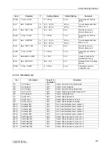
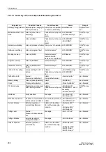
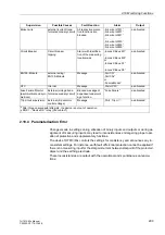
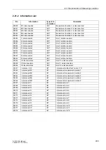
2.19.3.1 Summary of the most important Monitoring Functions
Supervision
Possible Causes
Fault Reaction
Alarm
Output
Auxiliary voltage failure External (aux. voltage) In-
ternal (converter)
Device out of operation
or alarm, if necessary
All LEDs dark
DOK
2
) drops
out
Measured value acqui-
sition
Internal (converter or
sampling)
Protection out of opera-
tion,
alarm
LED „ERROR“
„Error MeasurSys“
DOK
2
) drops
out
Internal (offset)
Protection out of opera-
tion,
alarm
LED „ERROR“
„Error Offset“
DOK
2
) drops
out
Hardware watchdog
Internal (processor failure) Device out of operation LED „ERROR“
DOK
2
) drops
out
Software watchdog
Internal (program flow)
Restart attempt
1)
LED „ERROR“
DOK
2
) drops
out
Working memory
Internal (RAM)
Restart attempt
1)
,
restart aborted
device out of operation
LED flashes
DOK
2
) drops
out
Program memory
Internal (EPROM)
Restart attempt
1)
LED „ERROR“
DOK
2
) drops
out
Parameter memory
Internal (EEPROM or
RAM)
Restart attempt
1)
LED „ERROR“
DOK
2
) drops
out
1 A/5 A/0.1 A setting
Jumper setting 1/5/0.1 A
wrong
Alarms,
Protection out of opera-
tion
„Error1A/5Awrong“
LED „ERROR“
DOK
2
) drops
out
Calibration data
internal
(device not calibrated)
Alarm,
Using default values
„Alarm adjustm.“
as allocated
Backup battery
Internal (backup battery)
Alarm
„Fail Battery“
as allocated
Clock
Time synchronization
Alarm
„Clock SyncError“
as allocated
P.C.B. modules
Module does not comply
with ordering number
Alarms,
Protection out of opera-
tion
„Error Board 0“ ...
„Error Board 7“ and if
necessary
„Error MeasurSys“
DOK
2
) drops
out
interfaces
faulty interface
Message
„Err. Module B“ ...
„Err. Module D“
as allocated
RTD box connection
RTD box not connected or
number does not match
No overload protection;
Alarm
„Fail: RTD-Box 1“ or
„Fail: RTD-Box 2“
as allocated
Current balance
External (system or
current transformers)
Alarm with identifica-
tion of the measuring
location
„Fail balan. IM1“
or
„Fail balan. IM2“
„Fail I balance“
as allocated
Voltage sum
internal
Measured value acquisi-
tion
Message
„Fail
Σ
U Ph-E“
as allocated
Voltage balance
external (system or
voltage transformer
Message
„Fail U balance“
as allocated
Phase sequence
External (system or
connections)
Alarm with identifica-
tion of the measuring
location
„FailPh.Seq IM1“
...
„FailPh.Seq IM5“
„Fail Ph. Seq. I“
„Fail Ph. Seq. U“
as allocated
Содержание SIPROTEC 7UT613 series
Страница 16: ...Contents 16 7UT613 63x Manual C53000 G1176 C160 2 Literature 631 Glossary 623 Index 633 ...
Страница 30: ...1 Introduction 30 7UT613 63x Manual C53000 G1176 C160 2 ...
Страница 506: ...A Appendix 506 7UT613 63x Manual C53000 G1176 C160 2 7UT633 D E ...
Страница 508: ...A Appendix 508 7UT613 63x Manual C53000 G1176 C160 2 7UT633 P Q ...
Страница 510: ...A Appendix 510 7UT613 63x Manual C53000 G1176 C160 2 7UT635 D E ...
Страница 512: ...A Appendix 512 7UT613 63x Manual C53000 G1176 C160 2 7UT635 P Q ...
Страница 515: ...A 2 Terminal Assignments 515 7UT613 63x Manual C53000 G1176 C160 2 7UT633 B ...
Страница 516: ...A Appendix 516 7UT613 63x Manual C53000 G1176 C160 2 7UT633 B Figure A 7 General diagram 7UT633 panel surface mounting ...
Страница 517: ...A 2 Terminal Assignments 517 7UT613 63x Manual C53000 G1176 C160 2 7UT633 N ...
Страница 518: ...A Appendix 518 7UT613 63x Manual C53000 G1176 C160 2 7UT633 N Figure A 8 General diagram 7UT633 panel surface mounting ...
Страница 519: ...A 2 Terminal Assignments 519 7UT613 63x Manual C53000 G1176 C160 2 7UT635 B ...
Страница 520: ...A Appendix 520 7UT613 63x Manual C53000 G1176 C160 2 7UT635 B Figure A 9 General diagram 7UT635 panel surface mounting ...
Страница 521: ...A 2 Terminal Assignments 521 7UT613 63x Manual C53000 G1176 C160 2 7UT635 N ...
Страница 522: ...A Appendix 522 7UT613 63x Manual C53000 G1176 C160 2 7UT635 N Figure A 10 General diagram 7UT635 panel surface mounting ...
Страница 622: ...A Appendix 622 7UT613 63x Manual C53000 G1176 C160 2 ...
Страница 632: ...Literature 632 7UT613 63x Manual C53000 G1176 C160 2 ...


