

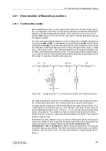


2.19 Monitoring Functions
291
7UT613/63x Manual
C53000-G1176-C160-2
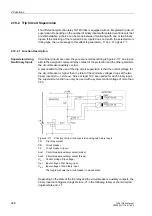
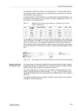
2.19.2.2 Setting Notes
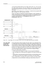
During configuration of the scope of functions, the number of binary inputs per trip
circuit was set at address
182
Trip Cir. Sup.
(see 2.1.3.1).
If the allocation of the required binary inputs does not match the selected monitoring
mode, a message to that effect appears (
„TripC ProgFail“
).
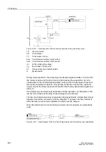
The trip circuit supervision can be switched at address
8201
TRIP Circuit
Supervision
ON
or
OFF
.
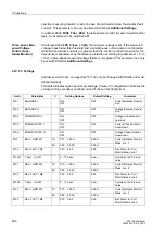
2.19.2.3 Settings
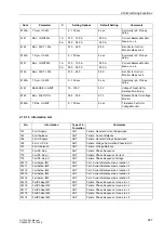
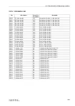
2.19.2.4 Information List
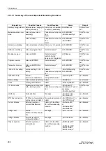
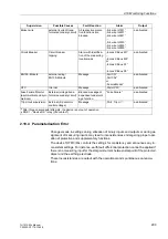
2.19.3 Malfunction Responses of the Device
Depending on the type of malfunction discovered, an alarm is given, a restart of the
processor system is initiated, or the device is taken out of service. If the fault is still
present after three restart attempts the protection system will take itself out of service
and indicate this condition by drop-off of the “Device OK” relay, thus indicating the
device failure. The red LED „ERROR“ on the device front lights up, provided that there
is an internal auxiliary voltage, and the green LED „RUN“ goes off. If the internal aux-
iliary voltage supply fails, all LEDs are dark. The following table shows a summary of
the most important monitoring functions and the fault reactions of the device.
Addr.
Parameter
Setting Options
Default Setting
Comments
8201
TRIP Cir. SUP.
ON
OFF
OFF
TRIP Circuit Supervision
No.
Information
Type of In-
formation
Comments
6851
>BLOCK TripC
SP
>BLOCK Trip circuit supervision
6852
>TripC trip rel
SP
>Trip circuit supervision: trip relay
6853
>TripC brk rel.
SP
>Trip circuit supervision: breaker relay
6861
TripC OFF
OUT
Trip circuit supervision OFF
6862
TripC BLOCKED
OUT
Trip circuit supervision is BLOCKED
6863
TripC ACTIVE
OUT
Trip circuit supervision is ACTIVE
6864
TripC ProgFail
OUT
Trip Circuit blk. Bin. input is not set
6865
FAIL: Trip cir.
OUT
Failure Trip Circuit
Содержание SIPROTEC 7UT613 series
Страница 16: ...Contents 16 7UT613 63x Manual C53000 G1176 C160 2 Literature 631 Glossary 623 Index 633 ...
Страница 30: ...1 Introduction 30 7UT613 63x Manual C53000 G1176 C160 2 ...
Страница 506: ...A Appendix 506 7UT613 63x Manual C53000 G1176 C160 2 7UT633 D E ...
Страница 508: ...A Appendix 508 7UT613 63x Manual C53000 G1176 C160 2 7UT633 P Q ...
Страница 510: ...A Appendix 510 7UT613 63x Manual C53000 G1176 C160 2 7UT635 D E ...
Страница 512: ...A Appendix 512 7UT613 63x Manual C53000 G1176 C160 2 7UT635 P Q ...
Страница 515: ...A 2 Terminal Assignments 515 7UT613 63x Manual C53000 G1176 C160 2 7UT633 B ...
Страница 516: ...A Appendix 516 7UT613 63x Manual C53000 G1176 C160 2 7UT633 B Figure A 7 General diagram 7UT633 panel surface mounting ...
Страница 517: ...A 2 Terminal Assignments 517 7UT613 63x Manual C53000 G1176 C160 2 7UT633 N ...
Страница 518: ...A Appendix 518 7UT613 63x Manual C53000 G1176 C160 2 7UT633 N Figure A 8 General diagram 7UT633 panel surface mounting ...
Страница 519: ...A 2 Terminal Assignments 519 7UT613 63x Manual C53000 G1176 C160 2 7UT635 B ...
Страница 520: ...A Appendix 520 7UT613 63x Manual C53000 G1176 C160 2 7UT635 B Figure A 9 General diagram 7UT635 panel surface mounting ...
Страница 521: ...A 2 Terminal Assignments 521 7UT613 63x Manual C53000 G1176 C160 2 7UT635 N ...
Страница 522: ...A Appendix 522 7UT613 63x Manual C53000 G1176 C160 2 7UT635 N Figure A 10 General diagram 7UT635 panel surface mounting ...
Страница 622: ...A Appendix 622 7UT613 63x Manual C53000 G1176 C160 2 ...
Страница 632: ...Literature 632 7UT613 63x Manual C53000 G1176 C160 2 ...