


1 Introduction
28
7UT613/63x Manual
C53000-G1176-C160-2
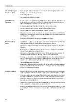
User-defined Logic
Functions (CFC)
• Freely programmable combination of internal and external signals for the imple-
mentation of user-defined logic functions
• All usual logic functions
• Time delays and limit value inquiries
Commissioning,
Operation
• Isolation of one side or measuring point for maintenance work: the isolated line or
measuring point is withdrawn from the differential protection system processing,
without affecting the remainder of the protection system
• Comprehensive support facilities for operation and commissioning
• Indication of all measured values, amplitudes and phase relation
• Indication of the calculated differential and restraint currents
• Integrated help tools can be visualised by means of a standard browser: Phasor di-
agrams of all currents of all sides and measuring locations of the protected object
are displayed as a graph.
• Connection and direction checks as well as interface check
Monitoring Func-
tions
• Availability of the device is greatly increased because of self-monitoring of the inter-
nal measurement circuits, power supply, hardware, and software
• Supervision of the current transformer secondary circuits of symmetry and phase
sequence
• Monitoring of the voltage transformer circuits (if voltage inputs are available) for
symmetry, voltage sum and phase rotation
• Supervision of the voltage transformer circuits (if voltage inputs are available) for
voltage failure with fast function blocking that measure undervoltages
• Checking the consistency of protection settings regarding the protected object and
possible assignment of the current inputs: Blocking of the differential protection
system in case of inconsistent settings which could lead to a malfunction
• Trip circuit supervision is possible.
• Broken wire supervision for the secondary CT circuits with fast phase segregated
blocking of the differential protection functions and the unbalanced load protection
in order to avoid spurious tripping.
Further Functions
• Battery-buffered real-time clock, which may be synchronised via a synchronisation
signal (e.g. DCF77, IRIG B via satellite receiver), binary input or system interface
• Continuous calculation and display of operational measured values on the front of
the device; indication of measured quantities of all sides of the protected object
• Fault event memory (trip log) for the last 8 network faults (faults in the power sys-
tem), with real-time assignment
• Fault recording memory and transmission of the data for analogue and user-defined
binary signals with a maximum time range of about 5s
• Switching Statistics: Recording of the trip commands issued by the device, as well
as recording of the fault current data and accumulation of the interrupted fault cur-
rents
Содержание SIPROTEC 7UT613 series
Страница 16: ...Contents 16 7UT613 63x Manual C53000 G1176 C160 2 Literature 631 Glossary 623 Index 633 ...
Страница 30: ...1 Introduction 30 7UT613 63x Manual C53000 G1176 C160 2 ...
Страница 506: ...A Appendix 506 7UT613 63x Manual C53000 G1176 C160 2 7UT633 D E ...
Страница 508: ...A Appendix 508 7UT613 63x Manual C53000 G1176 C160 2 7UT633 P Q ...
Страница 510: ...A Appendix 510 7UT613 63x Manual C53000 G1176 C160 2 7UT635 D E ...
Страница 512: ...A Appendix 512 7UT613 63x Manual C53000 G1176 C160 2 7UT635 P Q ...
Страница 515: ...A 2 Terminal Assignments 515 7UT613 63x Manual C53000 G1176 C160 2 7UT633 B ...
Страница 516: ...A Appendix 516 7UT613 63x Manual C53000 G1176 C160 2 7UT633 B Figure A 7 General diagram 7UT633 panel surface mounting ...
Страница 517: ...A 2 Terminal Assignments 517 7UT613 63x Manual C53000 G1176 C160 2 7UT633 N ...
Страница 518: ...A Appendix 518 7UT613 63x Manual C53000 G1176 C160 2 7UT633 N Figure A 8 General diagram 7UT633 panel surface mounting ...
Страница 519: ...A 2 Terminal Assignments 519 7UT613 63x Manual C53000 G1176 C160 2 7UT635 B ...
Страница 520: ...A Appendix 520 7UT613 63x Manual C53000 G1176 C160 2 7UT635 B Figure A 9 General diagram 7UT635 panel surface mounting ...
Страница 521: ...A 2 Terminal Assignments 521 7UT613 63x Manual C53000 G1176 C160 2 7UT635 N ...
Страница 522: ...A Appendix 522 7UT613 63x Manual C53000 G1176 C160 2 7UT635 N Figure A 10 General diagram 7UT635 panel surface mounting ...
Страница 622: ...A Appendix 622 7UT613 63x Manual C53000 G1176 C160 2 ...
Страница 632: ...Literature 632 7UT613 63x Manual C53000 G1176 C160 2 ...