


2.15 Overvoltage Protection
261
7UT613/63x Manual
C53000-G1176-C160-2
busbar, the pickup value must be set as reference value under address
5312
U>
, e.g.
1.20. When assigned to a measuring location, the value of phase-phase voltage must
be set under address
5311
U>
in Volt , e.g. 132. V at U
N sec
= 110 V (120 % of 110 V).
The corresponding delay time
T U>
(address
5313
) should amount to a few seconds
so that short-term overvoltages do not result in a trip.
The U>> stage is provided for high overvoltages of short duration. Here, an corre-
spondingly high pickup value is set, e.g. 1.3 to 1.5 times the rated voltage. If the over-
voltage protection is assigned to one side of the main protected object or the three-
phase busbar, the pickup value must be set as reference value under address
5315
U>>
, e.g. 1.30. When assigned to a measuring location, the value of phase-phase
voltage must be set under address
5314
U>>
in Volt , e.g. 130. V at U
N sec
= 100 V.
For the delay
T U>>
(address
5316
) 0.1 s to 0.5 s are sufficient.
In generators or transformers with voltage regulator, the settings also depend on the
speed with which the voltage regulator regulates voltage variations. The protection
must not intervene in the regulation process of the faultlessly functioning voltage reg-
ulator. The two-stage characteristic must therefore always be above the voltage time
characteristic of the regulation procedure.
All setting times are additional time delays which do not include the operating times
(measuring time, dropout time) of the protective function. If a delay time is set to
∞
,
this does not result in a trip, however, the pickup is indicated.
Dropout Ratio
The drop-out ratio can be adjusted to the operating conditions at address
5317
DOUT
RATIO
. This parameter can only be altered in DIGSI at
Additional Settings
.
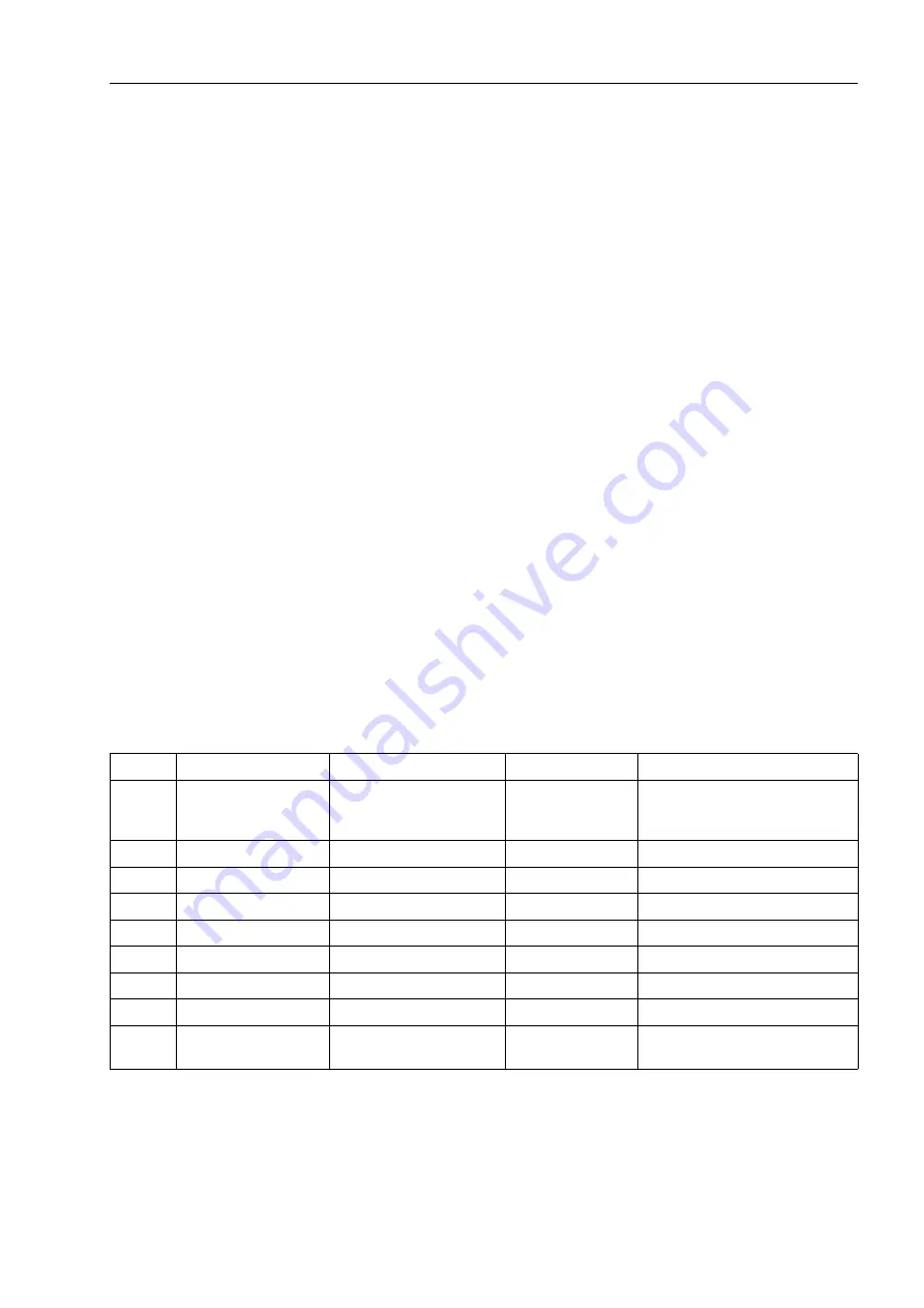
2.15.3 Settings
Addresses which have an appended "A" can only be changed with DIGSI, under Ad-
ditional Settings.
Addr.
Parameter
Setting Options
Default Setting
Comments
5301
OVERVOLTAGE
OFF
ON
Block relay
OFF
Overvoltage Protection
5311
U>
30.0 .. 170.0 V
115.0 V
U> Pickup
5312
U>
0.30 .. 1.70 U/UnS
1.15 U/UnS
Pick-up voltage U>
5313
T U>
0.00 .. 60.00 sec;
∞
3.00 sec
T U> Time Delay
5314
U>>
30.0 .. 170.0 V
130.0 V
U>> Pickup
5315
U>>
0.30 .. 1.70 U/UnS
1.30 U/UnS
Pick-up voltage U>>
5316
T U>>
0.00 .. 60.00 sec;
∞
0.50 sec
T U>> Time Delay
5317A
DOUT RATIO
0.90 .. 0.99
0.95
U>, U>> Drop Out Ratio
5318A
VALUES
U-ph-ph
U-ph-e
U-ph-ph
Measurement Values
Содержание SIPROTEC 7UT613 series
Страница 16: ...Contents 16 7UT613 63x Manual C53000 G1176 C160 2 Literature 631 Glossary 623 Index 633 ...
Страница 30: ...1 Introduction 30 7UT613 63x Manual C53000 G1176 C160 2 ...
Страница 506: ...A Appendix 506 7UT613 63x Manual C53000 G1176 C160 2 7UT633 D E ...
Страница 508: ...A Appendix 508 7UT613 63x Manual C53000 G1176 C160 2 7UT633 P Q ...
Страница 510: ...A Appendix 510 7UT613 63x Manual C53000 G1176 C160 2 7UT635 D E ...
Страница 512: ...A Appendix 512 7UT613 63x Manual C53000 G1176 C160 2 7UT635 P Q ...
Страница 515: ...A 2 Terminal Assignments 515 7UT613 63x Manual C53000 G1176 C160 2 7UT633 B ...
Страница 516: ...A Appendix 516 7UT613 63x Manual C53000 G1176 C160 2 7UT633 B Figure A 7 General diagram 7UT633 panel surface mounting ...
Страница 517: ...A 2 Terminal Assignments 517 7UT613 63x Manual C53000 G1176 C160 2 7UT633 N ...
Страница 518: ...A Appendix 518 7UT613 63x Manual C53000 G1176 C160 2 7UT633 N Figure A 8 General diagram 7UT633 panel surface mounting ...
Страница 519: ...A 2 Terminal Assignments 519 7UT613 63x Manual C53000 G1176 C160 2 7UT635 B ...
Страница 520: ...A Appendix 520 7UT613 63x Manual C53000 G1176 C160 2 7UT635 B Figure A 9 General diagram 7UT635 panel surface mounting ...
Страница 521: ...A 2 Terminal Assignments 521 7UT613 63x Manual C53000 G1176 C160 2 7UT635 N ...
Страница 522: ...A Appendix 522 7UT613 63x Manual C53000 G1176 C160 2 7UT635 N Figure A 10 General diagram 7UT635 panel surface mounting ...
Страница 622: ...A Appendix 622 7UT613 63x Manual C53000 G1176 C160 2 ...
Страница 632: ...Literature 632 7UT613 63x Manual C53000 G1176 C160 2 ...


