


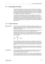


2.12 Reverse Power Protection
245
7UT613/63x Manual
C53000-G1176-C160-2
2.12
Reverse Power Protection
Reverse power protection is used to protect a turbo-generator unit on failure of energy
to the prime mover when the synchronous generator runs as a motor and drives the
turbine taking motoring energy from the network. This condition endangers the turbine
blades the and must be interrupted within a short time by tripping the network circuit-
breaker. For the generator, there is the additional risk that, in case of a malfunctioning
residual steam pass (defective stop valves) after the switching off of the circuit break-
ers, the turbine-generator-unit is speeded up, thus reaching an overspeed. For this
reason, the decoupling should only be performed after the detection of active power
input into the machine. The reverse power protection can be used as a criteria for the
decoupling in the system.
The reverse power protection can only be used for a three-phase protective objects.
This understands that the device is connected to a voltage transformer set and that
this voltage, together with an assigned corresponding current transformer, allows for
a logical calculation of the active power. This is therefore only possible for 7UT613 and
7UT633.
2.12.1 Function Description
Reverse Power De-
termination
The reverse power supervision in 7UT613/63x calculates the active power from the
symmetrical components of the fundamental waves of the voltages and currents.
There are two measurement methods:
• The "precise" measuring procedure is especially suited for reverse power protec-
tion on generators, as in this case a very low active power is calculated from a very
high apparent power (for small cos
ϕ)
. The positive sequence systems from voltag-
es and currents are used to obtain a very high accuracy of the last 16 cycles. The
evaluation of the positive phase-sequence systems makes the reverse power de-
termination independent of current and voltage asymmetries and corresponds to
actual loading of the drive end. By taking the error angles of the voltage and current
transformers into account, the active power component is exactly calculated even
with very high apparent powers and low cos
ϕ
. The angle correction is performed
by a correction angle
ϕ
corr
(see Subsection 2.1.4, "General System data"), which is
appropriately determined by the commissioning of the protective device in the
system (see Subsection "Installation and Commissioning", "Checking the Voltage
Connections and Polarity Check").
• The "fast" measurement also uses the positive-sequence components of currents
and voltages that are calculated over a cycle. A short tripping time is hereby
achieved. It is therefore well suited in system applications where short tripping times
are more desired than high accuracy of real power.
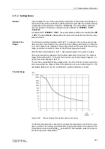
Pickup Seal-In Time
To ensure that frequently occurring short pickups can cause tripping, a selectable pro-
longation of these pickup signals is provided. Should new fault detection signals
appear within this seal-in time the pickup is maintained, so that a delayed tripping can
take place.
Delay and Logic
Two delay times are available for the delay of the trip command.
When used as a reverse power protection for generators, bridging a perhaps short
power input during synchronisation or during power swings caused by system faults,
the trip command is delayed by a selectable time
T-SV-OPEN
. In case of a closed
Содержание SIPROTEC 7UT613 series
Страница 16: ...Contents 16 7UT613 63x Manual C53000 G1176 C160 2 Literature 631 Glossary 623 Index 633 ...
Страница 30: ...1 Introduction 30 7UT613 63x Manual C53000 G1176 C160 2 ...
Страница 506: ...A Appendix 506 7UT613 63x Manual C53000 G1176 C160 2 7UT633 D E ...
Страница 508: ...A Appendix 508 7UT613 63x Manual C53000 G1176 C160 2 7UT633 P Q ...
Страница 510: ...A Appendix 510 7UT613 63x Manual C53000 G1176 C160 2 7UT635 D E ...
Страница 512: ...A Appendix 512 7UT613 63x Manual C53000 G1176 C160 2 7UT635 P Q ...
Страница 515: ...A 2 Terminal Assignments 515 7UT613 63x Manual C53000 G1176 C160 2 7UT633 B ...
Страница 516: ...A Appendix 516 7UT613 63x Manual C53000 G1176 C160 2 7UT633 B Figure A 7 General diagram 7UT633 panel surface mounting ...
Страница 517: ...A 2 Terminal Assignments 517 7UT613 63x Manual C53000 G1176 C160 2 7UT633 N ...
Страница 518: ...A Appendix 518 7UT613 63x Manual C53000 G1176 C160 2 7UT633 N Figure A 8 General diagram 7UT633 panel surface mounting ...
Страница 519: ...A 2 Terminal Assignments 519 7UT613 63x Manual C53000 G1176 C160 2 7UT635 B ...
Страница 520: ...A Appendix 520 7UT613 63x Manual C53000 G1176 C160 2 7UT635 B Figure A 9 General diagram 7UT635 panel surface mounting ...
Страница 521: ...A 2 Terminal Assignments 521 7UT613 63x Manual C53000 G1176 C160 2 7UT635 N ...
Страница 522: ...A Appendix 522 7UT613 63x Manual C53000 G1176 C160 2 7UT635 N Figure A 10 General diagram 7UT635 panel surface mounting ...
Страница 622: ...A Appendix 622 7UT613 63x Manual C53000 G1176 C160 2 ...
Страница 632: ...Literature 632 7UT613 63x Manual C53000 G1176 C160 2 ...


