


2 Functions
228
7UT613/63x Manual
C53000-G1176-C160-2
Environment Tem-
perature Influence
in Thermal Replica
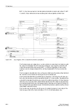
If the environmental or coolant temperature must be taken into consideration in the
thermal replica, the device must be informed as to which of the temperature detectors
(RTD = Resistance Temperature Detector) is applicable. With RTD-box 7XV5662–
xAD up to 6 detectors are possible, with 2 boxes up to 12. In case of connection of one
RTD-box, under address
4210
TEMPSENSOR RTD
the number of the applicable tem-
perature detector (1 to 6) must be set, in case of connection of two RTD-boxes under
address
4211
TEMPSENSOR RTD
(1 to 12). Only such address is always available that
corresponds with the setting in accordance with the functional scope (section 2.1.3.1)
under address
191
RTD CONNECTION
.
All calculations are performed with standardised quantities. The ambient temperature
must also be standardised. The temperature with nominal current of the protected
object is used as standardised quantity. Set this temperature under address
4212
TEMP. RISE I
in
°
C or under address
4213
TEMP. RISE I
in
°
F, depending on
which temperature unit was selected in accordance with section 2.1.4.
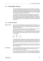
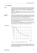
Alarm Stages with
Thermal Replica
By setting a thermal alarm stage
Θ
ALARM
(address
4204
) an alarm can be released
before the tripping temperature is reached, so that a trip can be avoided by early load
reduction or by switching over. The percentage refers to the tripping temperature rise.
Note that the final temperature rise is proportional to the square of the current.
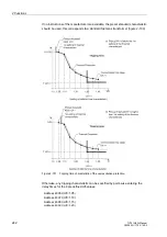
Example:
k-factor k = 1.1
Nominal current flow results in the following temperature rise:
The thermal warning stage should be set above temperature rise at nominal current
(82.6 %). A sensible setting value would be
Θ
ALARM
= 90 %.
The current overload alarm setpoint
I ALARM
(address
4205
) is referred to the rated
current of the side and should be set equal to or slightly below the permissible contin-
uous current k ·
I
N Obj
. It can also be used instead of the thermal alarm stage. In this
case, the thermal alarm stage is set to 100 % and is thus virtually ineffective.
Emergency Start
for Motors
The run-on time value to be entered at address
4208
T EMERGENCY
must ensure that,
after an emergency start and dropout of the binary input , the trip command is blocked
until the thermal replica has fallen below the dropout threshold. This parameter can
only be set with DIGSI under
Additional Settings
.
The startup itself is only recognised if the startup current
4209
set in address
I MOTOR
START
is exceeded. Under each load and voltage condition during motor start, the
value must be overshot by the actual startup current. With short-time permissible over-
load the value must not be reached. This parameter can only be set with DIGSI under
Additional Settings
. For other protected objects retain setting
∞
. The emergency
start is thus disabled.
Temperature Detec-
tor for Hot-spot Cal-
culation
For the hot-spot calculation according to IEC 60354 the device must be informed on
the type of resistance temperature detectors (RTD) that will be used for measuring the
oil temperature, the one relevant for the hot-spot calculation and ageing determina-
tion. With a RTD-box 7XV5662x–xAD up to 6 detectors are possible, with 2 boxes up
to 12. On connection of
one
RTD-box set under address
4220
OIL-DET. RTD
the
number of the relevant temperature detector (
1
to
6
), on connection of
two
RTD-boxes
under address
4221
OIL-DET. RTD
(
1
to
12
). Only
such
address is always available
Содержание SIPROTEC 7UT613 series
Страница 16: ...Contents 16 7UT613 63x Manual C53000 G1176 C160 2 Literature 631 Glossary 623 Index 633 ...
Страница 30: ...1 Introduction 30 7UT613 63x Manual C53000 G1176 C160 2 ...
Страница 506: ...A Appendix 506 7UT613 63x Manual C53000 G1176 C160 2 7UT633 D E ...
Страница 508: ...A Appendix 508 7UT613 63x Manual C53000 G1176 C160 2 7UT633 P Q ...
Страница 510: ...A Appendix 510 7UT613 63x Manual C53000 G1176 C160 2 7UT635 D E ...
Страница 512: ...A Appendix 512 7UT613 63x Manual C53000 G1176 C160 2 7UT635 P Q ...
Страница 515: ...A 2 Terminal Assignments 515 7UT613 63x Manual C53000 G1176 C160 2 7UT633 B ...
Страница 516: ...A Appendix 516 7UT613 63x Manual C53000 G1176 C160 2 7UT633 B Figure A 7 General diagram 7UT633 panel surface mounting ...
Страница 517: ...A 2 Terminal Assignments 517 7UT613 63x Manual C53000 G1176 C160 2 7UT633 N ...
Страница 518: ...A Appendix 518 7UT613 63x Manual C53000 G1176 C160 2 7UT633 N Figure A 8 General diagram 7UT633 panel surface mounting ...
Страница 519: ...A 2 Terminal Assignments 519 7UT613 63x Manual C53000 G1176 C160 2 7UT635 B ...
Страница 520: ...A Appendix 520 7UT613 63x Manual C53000 G1176 C160 2 7UT635 B Figure A 9 General diagram 7UT635 panel surface mounting ...
Страница 521: ...A 2 Terminal Assignments 521 7UT613 63x Manual C53000 G1176 C160 2 7UT635 N ...
Страница 522: ...A Appendix 522 7UT613 63x Manual C53000 G1176 C160 2 7UT635 N Figure A 10 General diagram 7UT635 panel surface mounting ...
Страница 622: ...A Appendix 622 7UT613 63x Manual C53000 G1176 C160 2 ...
Страница 632: ...Literature 632 7UT613 63x Manual C53000 G1176 C160 2 ...


