


2 Functions
194
7UT613/63x Manual
C53000-G1176-C160-2
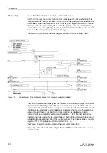
rion, the feedback information of the assigned breaker must inform the device about
the breaker position.
The time overcurrent protection for earth current allows the breaker criterion only if an
unequivocal relationship exists between its assigned side or measuring location and
the feedback information of the breaker (
SwitchgCBaux S1
,
SwitchgCBaux S2
to
SwitchgCBaux M5
, addresses
831
to
840
).
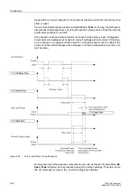
Timers
There are no specific procedures on how to set the delay times
CB Open Time
at ad-
dresses
1711
),
Active Time
(address
1712
) and
Stop Time
(address
1713)
.
These time delays must be based on the specific loading characteristics of the equip-
ment being protected, and should be set to allow short-term overloads associated with
dynamic cold load conditions.
Cold Load Pickup
Values
The dynamic pickup values and time delays associated with the time overcurrent
stages are set in the related addresses of the stages themselves.
2.6.3
Settings
Addr.
Parameter
Setting Options
Default Setting
Comments
1701
COLDLOAD PICKUP
OFF
ON
OFF
Cold-Load-Pickup Function
1702
Start CLP Phase
No Current
Breaker Contact
No Current
Start Condition CLP for O/C Phase
1703
Start CLP 3I0
No Current
Breaker Contact
No Current
Start Condition CLP for O/C 3I0
1704
Start CLP Earth
No Current
Breaker Contact
No Current
Start Condition CLP for O/C Earth
1705
Start CLP Ph 2
No Current
Breaker Contact
No Current
Start Condition CLP for O/C Phase 2
1706
Start CLP Ph 3
No Current
Breaker Contact
No Current
Start Condition CLP for O/C Phase 3
1707
Start CLP 3I0 2
No Current
Breaker Contact
No Current
Start Condition CLP for O/C 3I0 2
1708
Start CLP 3I0 3
No Current
Breaker Contact
No Current
Start Condition CLP for O/C 3I0 3
1709
Start CLP E 2
No Current
Breaker Contact
No Current
Start Condition CLP for O/C Earth 2
1711
CB Open Time
0 .. 21600 sec
3600 sec
Circuit Breaker OPEN Time
1712
Active Time
1 .. 21600 sec
3600 sec
Active Time
1713
Stop Time
1 .. 600 sec;
∞
600 sec
Stop Time
Содержание SIPROTEC 7UT613 series
Страница 16: ...Contents 16 7UT613 63x Manual C53000 G1176 C160 2 Literature 631 Glossary 623 Index 633 ...
Страница 30: ...1 Introduction 30 7UT613 63x Manual C53000 G1176 C160 2 ...
Страница 506: ...A Appendix 506 7UT613 63x Manual C53000 G1176 C160 2 7UT633 D E ...
Страница 508: ...A Appendix 508 7UT613 63x Manual C53000 G1176 C160 2 7UT633 P Q ...
Страница 510: ...A Appendix 510 7UT613 63x Manual C53000 G1176 C160 2 7UT635 D E ...
Страница 512: ...A Appendix 512 7UT613 63x Manual C53000 G1176 C160 2 7UT635 P Q ...
Страница 515: ...A 2 Terminal Assignments 515 7UT613 63x Manual C53000 G1176 C160 2 7UT633 B ...
Страница 516: ...A Appendix 516 7UT613 63x Manual C53000 G1176 C160 2 7UT633 B Figure A 7 General diagram 7UT633 panel surface mounting ...
Страница 517: ...A 2 Terminal Assignments 517 7UT613 63x Manual C53000 G1176 C160 2 7UT633 N ...
Страница 518: ...A Appendix 518 7UT613 63x Manual C53000 G1176 C160 2 7UT633 N Figure A 8 General diagram 7UT633 panel surface mounting ...
Страница 519: ...A 2 Terminal Assignments 519 7UT613 63x Manual C53000 G1176 C160 2 7UT635 B ...
Страница 520: ...A Appendix 520 7UT613 63x Manual C53000 G1176 C160 2 7UT635 B Figure A 9 General diagram 7UT635 panel surface mounting ...
Страница 521: ...A 2 Terminal Assignments 521 7UT613 63x Manual C53000 G1176 C160 2 7UT635 N ...
Страница 522: ...A Appendix 522 7UT613 63x Manual C53000 G1176 C160 2 7UT635 N Figure A 10 General diagram 7UT635 panel surface mounting ...
Страница 622: ...A Appendix 622 7UT613 63x Manual C53000 G1176 C160 2 ...
Страница 632: ...Literature 632 7UT613 63x Manual C53000 G1176 C160 2 ...


