


2 Functions
180
7UT613/63x Manual
C53000-G1176-C160-2
Pickup, Trip
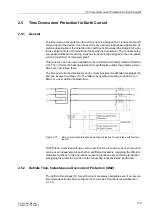
Two definite time stages are available for the earth current.
For the IE>> stage, the current measured at the assigned 1-phase current input is
compared with the setting value
IE>>
. Current above the pickup value is detected and
annunciated. When the delay time
T IE>>
has expired, tripping command is issued.
The reset value is approximately 95 % below the pickup value for currents above
I
N
.
Lower values require a higher hysteresis in order to avoid intermittent pickup on cur-
rents near the pickup value (e.g. 20 % at 0.1 ·
I
N
).
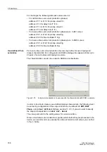
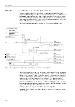
The following figure shows the logic diagram for the high-current stage
IE>>
.
Figure 2-78
Logic diagram of the high-current stage I
E
>> for earth current (simplified)
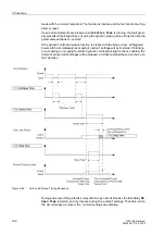
The current detected at the assigned one-phase current measuring input is addition-
ally compared with setting value
IE>
. An annunciation is generated if the value is ex-
ceeded. If inrush restraint is used, a frequency analysis is performed first. If an inrush
condition is detected, pickup annunciation is suppressed and an inrush message is
output instead. If there is no inrush or if inrush restraint is disabled, a tripping
command will be output after expiration of delay time
T IE>
. If inrush restraint is
enabled and inrush current is detected, there will be no tripping. Nevertheless, an an-
nunciation is generated indicating that the time expired. The dropout value is roughly
equal to 95% of the pickup value for currents
I
> 0,3 ·
I
N
.
The Figure shows the logic diagram of the overcurrent stage
IE>
.
The pickup values for each of the stages
IE>
and
IE>>
and the delay times can be
set individually.
Содержание SIPROTEC 7UT613 series
Страница 16: ...Contents 16 7UT613 63x Manual C53000 G1176 C160 2 Literature 631 Glossary 623 Index 633 ...
Страница 30: ...1 Introduction 30 7UT613 63x Manual C53000 G1176 C160 2 ...
Страница 506: ...A Appendix 506 7UT613 63x Manual C53000 G1176 C160 2 7UT633 D E ...
Страница 508: ...A Appendix 508 7UT613 63x Manual C53000 G1176 C160 2 7UT633 P Q ...
Страница 510: ...A Appendix 510 7UT613 63x Manual C53000 G1176 C160 2 7UT635 D E ...
Страница 512: ...A Appendix 512 7UT613 63x Manual C53000 G1176 C160 2 7UT635 P Q ...
Страница 515: ...A 2 Terminal Assignments 515 7UT613 63x Manual C53000 G1176 C160 2 7UT633 B ...
Страница 516: ...A Appendix 516 7UT613 63x Manual C53000 G1176 C160 2 7UT633 B Figure A 7 General diagram 7UT633 panel surface mounting ...
Страница 517: ...A 2 Terminal Assignments 517 7UT613 63x Manual C53000 G1176 C160 2 7UT633 N ...
Страница 518: ...A Appendix 518 7UT613 63x Manual C53000 G1176 C160 2 7UT633 N Figure A 8 General diagram 7UT633 panel surface mounting ...
Страница 519: ...A 2 Terminal Assignments 519 7UT613 63x Manual C53000 G1176 C160 2 7UT635 B ...
Страница 520: ...A Appendix 520 7UT613 63x Manual C53000 G1176 C160 2 7UT635 B Figure A 9 General diagram 7UT635 panel surface mounting ...
Страница 521: ...A 2 Terminal Assignments 521 7UT613 63x Manual C53000 G1176 C160 2 7UT635 N ...
Страница 522: ...A Appendix 522 7UT613 63x Manual C53000 G1176 C160 2 7UT635 N Figure A 10 General diagram 7UT635 panel surface mounting ...
Страница 622: ...A Appendix 622 7UT613 63x Manual C53000 G1176 C160 2 ...
Страница 632: ...Literature 632 7UT613 63x Manual C53000 G1176 C160 2 ...


