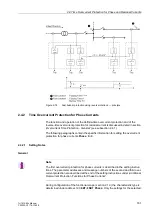


2.4 Time Overcurrent Protection for Phase and Residual Currents
175
7UT613/63x Manual
C53000-G1176-C160-2
This means that a pickup will only occur if a current of about 1.1 times the setting value
is present.
The current value is set in address
2221
or
2222
3I0p
. The most relevant for this
setting is the minimum appearing earth fault current. Please consider that measuring
tolerances may be higher with multiple measuring locations due to summation errors.
The corresponding time multiplier is set in address
2224
D 3I0p
. This has to be co-
ordinated with the grading coordination chart of the network. For earth currents with
earthed network, you can mostly set up a separate grading coordination chart with
shorter delay times.
If you set a very small pickup value, consider that the inrush restraint function cannot
operate below 10 % nominal current (lower limit of harmonic filtering). An adequate
time delay could be reasonable if inrush restraint is used.
The time multiplier can also be set to
∞
. If set to infinity, the pickup of this function will
be indicated but the stage will not trip after pickup. If the 3I0p stage is not required at
all, select address
122
DMT/IDMT 3I0
=
Definite Time
during configuration of
the protection function.
If under address
2225
TOC DROP-OUT
the
Disk Emulation
is set, a dropout in ac-
cordance with the dropout characteristic occurs, as described in section „Dropout Be-
haviour“
Dynamic Cold Load
Pickup
An alternative set of pickup values can be set for each stage. It may be selected au-
tomatically in a dynamic manner during operation. The following alternative values are
set for the stages here (section 2.6).
for definite time overcurrent protection 3
I
0:
• address
2311
or
2312
for pickup value
3I0>>
,
• address
2313
for delay time
T 3I0>>
,
• address
2314
or
2315
for pickup value
3I0>
,
• address
2316
for delay time
T 3I0>
,
for inverse time overcurrent protection 3
I
0 acc. to IEC characteristics:
• address
2321
or
2322
for pickup value
3I0p
,
• address
2323
for time multiplier
T 3I0p
;
for inverse time overcurrent protection 3
I
0 acc. to ANSI characteristics:
• address
2321
or
2322
for pickup value
3I0p
,
• address
2324
for time multiplier
D 3I0p
;
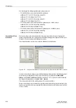
User-Defined
Curves
For inverse time overcurrent protection the user may define his own tripping and
dropout characteristic. For configuration in DIGSI a dialogue box appears. Enter up
to 20 pairs of current and tripping time values.
The procedure is the same as for „Phase Current Stages“ under „User-specific Char-
acteristics“ (see section 2.4.2.1).
To create a user defined tripping characteristic, the following must have been set for
configuration of the scope of functions: address
122
DMT/IDMT 3I0
the option
User
Defined PU
. Should you also wish to specify the dropout characteristic, select option
User def. Reset
.
Inrush Restraint
At address
2202
InRushRest. 3I0
of the general settings, the inrush restraint can
be enabled (
ON
) or disabled (
OFF
). Especially for transformers and if overcurrent time
Содержание SIPROTEC 7UT613 series
Страница 16: ...Contents 16 7UT613 63x Manual C53000 G1176 C160 2 Literature 631 Glossary 623 Index 633 ...
Страница 30: ...1 Introduction 30 7UT613 63x Manual C53000 G1176 C160 2 ...
Страница 506: ...A Appendix 506 7UT613 63x Manual C53000 G1176 C160 2 7UT633 D E ...
Страница 508: ...A Appendix 508 7UT613 63x Manual C53000 G1176 C160 2 7UT633 P Q ...
Страница 510: ...A Appendix 510 7UT613 63x Manual C53000 G1176 C160 2 7UT635 D E ...
Страница 512: ...A Appendix 512 7UT613 63x Manual C53000 G1176 C160 2 7UT635 P Q ...
Страница 515: ...A 2 Terminal Assignments 515 7UT613 63x Manual C53000 G1176 C160 2 7UT633 B ...
Страница 516: ...A Appendix 516 7UT613 63x Manual C53000 G1176 C160 2 7UT633 B Figure A 7 General diagram 7UT633 panel surface mounting ...
Страница 517: ...A 2 Terminal Assignments 517 7UT613 63x Manual C53000 G1176 C160 2 7UT633 N ...
Страница 518: ...A Appendix 518 7UT613 63x Manual C53000 G1176 C160 2 7UT633 N Figure A 8 General diagram 7UT633 panel surface mounting ...
Страница 519: ...A 2 Terminal Assignments 519 7UT613 63x Manual C53000 G1176 C160 2 7UT635 B ...
Страница 520: ...A Appendix 520 7UT613 63x Manual C53000 G1176 C160 2 7UT635 B Figure A 9 General diagram 7UT635 panel surface mounting ...
Страница 521: ...A 2 Terminal Assignments 521 7UT613 63x Manual C53000 G1176 C160 2 7UT635 N ...
Страница 522: ...A Appendix 522 7UT613 63x Manual C53000 G1176 C160 2 7UT635 N Figure A 10 General diagram 7UT635 panel surface mounting ...
Страница 622: ...A Appendix 622 7UT613 63x Manual C53000 G1176 C160 2 ...
Страница 632: ...Literature 632 7UT613 63x Manual C53000 G1176 C160 2 ...


